ProSoft Technology MVI56E-MNETCR User Manual
Page 98
Reference
MVI56E-MNETCR ♦ ControlLogix Platform
User Manual
Modbus TCP/IP Multi Client Enhanced Communications Module for Remote Chassis
Page 98 of 159
ProSoft Technology, Inc.
June 14, 2011
5.2.2 Backplane Data Transfer
The MVI56E-MNETCR module communicates directly over the ControlLogix
backplane. Data is paged between the module and the ControlLogix processor
across the backplane using the module's input and output images. The update
frequency of the images is determined by the scheduled scan rate defined by the
user for the module and the communication load on the module. Typical updates
are in the range of 1 to 10 milliseconds.
This bi-directional transference of data is accomplished by the module filling in
data in the module's input image to send to the processor. Data in the input
image is placed in the Controller Tags in the processor by the ladder logic. The
input image for the module is set to 42 words. This data is transferred in the
scheduled I/O timeslot.
The processor inserts data to the module's output image to transfer to the
module. The module's program extracts the data and places it in the module's
internal database. The output image for the module is set to 42 words. This data
is transferred in the scheduled I/O timeslot.
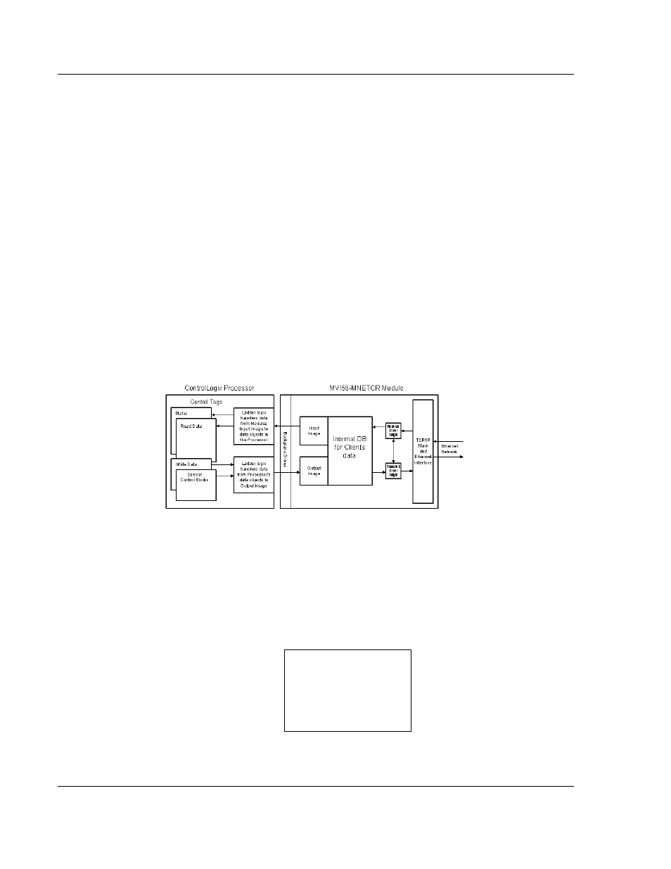
The following illustration shows the data transfer method used to move data
between the ControlLogix processor, the MVI56E-MNETCR module and the
Modbus TCP/IP Network.
All data transferred between the module and the processor over the backplane is
through the input and output images. Ladder logic must be written in the
ControlLogix processor to interface the input and output image data with data
defined in the Controller Tags. All data used by the module is stored in its internal
database. This database is defined as a virtual Modbus data table with
addresses from 0 (40001 Modbus) to 4999 (45000 Modbus). The following
illustration shows the layout of the database:
Module’s Internal Database Structure
5000 registers for user data
0
Register Data
4999