ProSoft Technology MVI56E-MNETCR User Manual
Page 14
Start Here
MVI56E-MNETCR ♦ ControlLogix Platform
User Manual
Modbus TCP/IP Multi Client Enhanced Communications Module for Remote Chassis
Page 14 of 159
ProSoft Technology, Inc.
June 14, 2011
1.5
Installing the Module in the Rack
If you have not already installed and configured your ControlLogix processor and
power supply, please do so before installing the MVI56E-MNETCR module.
Refer to your Rockwell Automation product documentation for installation
instructions.
Warning: You must follow all safety instructions when installing this or any other electronic
devices. Failure to follow safety procedures could result in damage to hardware or data, or even
serious injury or death to personnel. Refer to the documentation for each device you plan to
connect to verify that suitable safety procedures are in place before installing or servicing the
device.
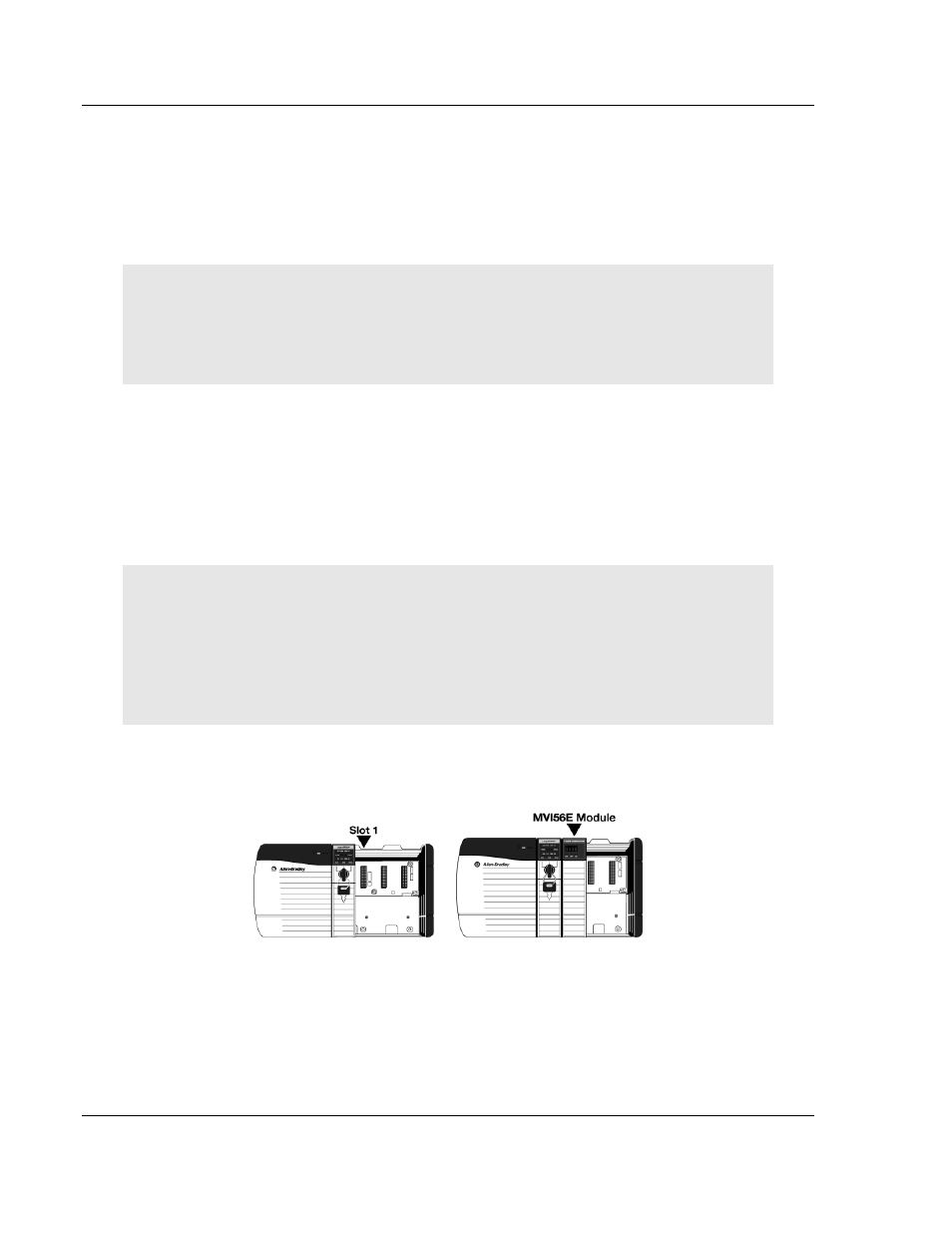
After you have checked the placement of the jumpers, insert the MVI56E-
MNETCR into the ControlLogix chassis. Use the same technique recommended
by Rockwell Automation to remove and install ControlLogix modules.
You can install or remove ControlLogix system components while chassis power
is applied and the system is operating. However, please note the following
warning.
Warning: When you insert or remove the module while backplane power is on, an electrical arc
can occur. An electrical arc can cause personal injury or property damage by sending an
erroneous signal to your system’s actuators. This can cause unintended machine motion or loss of
process control. Electrical arcs may also cause an explosion when they happen in a hazardous
environment. Verify that power is removed or the area is non-hazardous before proceeding.
Repeated electrical arcing causes excessive wear to contacts on both the module and its mating
connector. Worn contacts may create electrical resistance that can affect module operation.
1 Align the module with the top and bottom guides, and then slide it into the
rack until the module is firmly against the backplane connector.
2 With a firm, steady push, snap the module into place.
3 Check that the holding clips on the top and bottom of the module are securely
in the locking holes of the rack.