ProSoft Technology MVI56E-MNETCR User Manual
Page 23
MVI56E-MNETCR ♦ ControlLogix Platform
Start Here
Modbus TCP/IP Multi Client Enhanced Communications Module for Remote Chassis
User Manual
ProSoft Technology, Inc.
Page 23 of 159
June 14, 2011
2 Click CIP
P
ATH
E
DIT
to open the
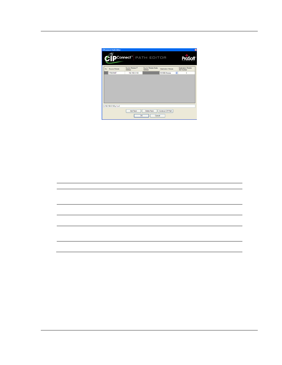
CIPconnect Path Editor dialog box.
The CIPconnect Path Editor allows you to define the path between the PC and
the MVI56E-MNETCR module. The first connection from the PC is always a
1756-ENBT (Ethernet/IP) module.
Each row corresponds to a physical rack in the CIP path.
If the MVI56E-MNETCR module is located in the same rack as the first 1756-
ENBT module, select
R
ACK
N
O
.
1 and configure the associated parameters.
If the MVI56E-MNETCR is available in a remote rack (accessible through
ControlNet or Ethernet/IP), include all racks (by using the A
DD
R
ACK
button).
Parameter
Description
Source Module
Source module type. This field is automatically selected
depending on the destination module of the last rack
(1756-CNB or 1756-ENBT).
Source Module IP Address
IP address of the source module (only applicable for
1756-ENBT)
Source Module Node Address
Node address of the source module (only applicable for
1756-CNB)
Destination Module
Select the destination module associated to the source module
in the rack. The connection between the source and destination
modules is performed through the backplane.
Destination Module Slot Number
The slot number where the destination MVI56E module is
located.
To use the CIPconnect Path Editor, follow these steps.
1 Configure the path between the 1756-ENBT connected to your PC and the
MVI56E-MNETCR module.
o
If the module is located in a remote rack, add more racks to configure the
full path.
o
The path can only contain ControlNet or Ethernet/IP networks.
o
The maximum number of supported racks is six.
2 Click C
ONSTRUCT
CIP
P
ATH
to build the path in text format
3 Click OK
to confirm the configured path.