ProSoft Technology MVI69-FLN User Manual
Page 65
Start Here
MVI69-FLN ♦ CompactLogix Platform
FA Control Network Communication Module
ProSoft Technology, Inc.
Page 65 of 137
November 3, 2008
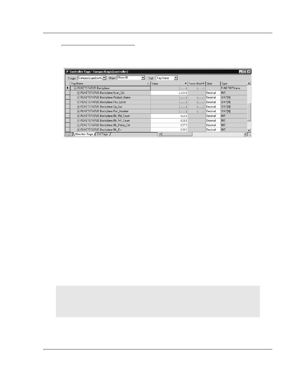
Checking the Backplane status
Monitor the FLNETSTATUS.Backplane controller tag for information about
backplane status.
1.20.5 Transferring Data
The sample ladder logic automatically updates the data with the
FLNETDATA.Output and FLNETDATA.Input controller tags. The Area 1 data is
divided into blocks 1 to 3. The Area 2 data is divided into blocks 4 to 35. Each
block contains up to 240 words of data.
The data received from the remote FL-net node to the MVI69-FLN module is
automatically "reassembled" from the input blocks into the FLNETDATA.Intput
controller tag (according to each block ID). Also, the data to transfer from the
module to the remote FL-net node is copied from the FLNETDATA.Output
controller tag into the output blocks according to its block ID. This logic is already
handled by the sample ladder program supplied by ProSoft.
For this example, use the following MVI69-FLN Area1 and Area 2 settings in the
FLNET.CFG configuration file:
Area 1 Top : 0 #0...511 top address for area 1
Area 1 Size : 50 #0...512 area 1 data size in words (0=not used)
Area 2 Top : 0 #0...8191 top address for area 1
Area 2 Size : 100 #0...8192 area 2 data size in words (0=not used)
BP Area 1 Top : 50 #0...511 top address for area 1
BP Area 1 Size: 50 #0...512 area 1 data size in words (0=none transferred)
BP Area 2 Top : 100 #0...8191 top address for area 1
BP Area 2 Size: 100 #0...8192 area 2 data size in words (0=none transferred)
Important: The module only generates the blocks required to transfer the data you configured. For
this example only one Area 1 block and one Area 2 blocks are required, so only blocks 1 to 4 are
used for data transfer. The larger the areas, the more blocks are required to transfer data (and the
more time is required to update the whole block).