Configure the node number, Configure, Node number – ProSoft Technology MVI69-FLN User Manual
Page 37
Start Here
MVI69-FLN ♦ CompactLogix Platform
FA Control Network Communication Module
ProSoft Technology, Inc.
Page 37 of 137
November 3, 2008
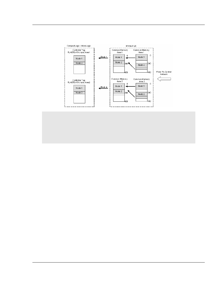
The following illustration shows how the data transfer would occur for this
example:
Important: A1 Network Start and A2 Network Start parameters refer to the start offset within each
node’s area. So for this example node 2 mapping was configured as:
A1 Network Start = A2 Network Start = 100
Therefore, the A1/A2 Network Start offsets do not indicate the absolute Common Memory offset
(340 for this example). It indicates the starting offset within that specific node’s area (100 for this
example).
1.13 Configure the Node Number
Configure the MVI69-FLN module with a node number of 40. The last digit of the
IP address is used to denote the node number of the module.
Refer to the configuration file WATTCP.CFG and configure both parameters as
follows:
my_ip=192.168.250.40
netmask=255.255.255.0