PLANET WGSW-50040 User Manual
Page 110
12-7
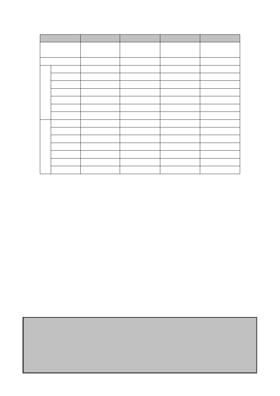
Bridge Name
Switch1
Switch2
Switch3
Switch4
Bridge MAC
Address
…00-00-01
…00-00-02
…00-00-03
…00-00-04
Bridge Priority
32768
32768
32768
32768
P
o
rt
P
ri
o
ri
ty
Port 1
128
128
128
Port 2
128
128
128
Port 3
128
128
Port 4
128
128
Port 5
128
128
Port 6
128
128
Port 7
128
128
R
out
e
C
os
t
Port 1
200000
200000
200000
Port 2
200000
200000
200000
Port 3
200000
200000
Port 4
200000
200000
Port 5
200000
200000
Port 6
200000
200000
Port 7
200000
200000
By default, the MSTP establishes a tree topology (in blue lines) rooted with SwitchA. The ports marked with
“x” are in the discarding status, and the other ports are in the forwarding status.
Configurations Steps:
Step 1: Configure port to VLAN mapping:
Create VLAN 20, 30, 40, 50 in Switch2, Switch3 and Switch4.
Set ports 1-7 as trunk ports in Switch2 Switch3 and Switch4.
Step 2: Set Switch2, Switch3 and Switch4 in the same MSTP:
Set Switch2, Switch3 and Switch4 to have the same region name as mstp.
Map VLAN 20 and VLAN 30 in Switch2, Switch3 and Switch4 to Instance 3; Map VLAN 40 and VLAN
50 in Switch2, Switch3 and Switch4 to Instance 4.
Step 3: Set Switch3 as the root bridge of Instance 3; Set Switch4 as the root bridge of Instance 4
Set the bridge priority of Instance 3 in Switch3 as 0.
Set the bridge priority of Instance 4 in Switch4 as 0.
The detailed configuration is listed below:
Switch2:
Switch2(config)#vlan 20
Switch2(Config-Vlan20)#exit
Switch2(config)#vlan 30
Switch2(Config-Vlan30)#exit
Switch2(config)#vlan 40
Switch2(Config-Vlan40)#exit
Switch2(config)#vlan 50