Emerson MPR15 Series User Manual
Page 29
Operation 29
25A Switch Mode Rectifier
NT5C06B / C Installation and User Manual
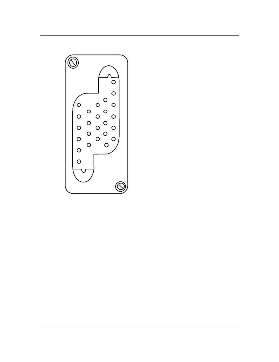
Figure 3 - Signal Connector
Connector housing:
AMP 211149-1
Crimp type pins (24-20 AWG):
AMP 66103-1
PCB solder/wire wrap pins:
AMP 66460-7
The 'SENSE' alarm contact closes to indicate that the remote sense leads are
open.
The signals normally connected to Astec controllers are indicated below.
1
1 - REMOTE EQL
2 - SENSING RG +
3 - SENSING RC -
4 - TEMPORARY RELEASE
5 - REMOTE HVSD RESET
6 - REMOTE HVSD
7 - RFA NC
8 - Not Connected
9 - FAN ALARM NC
10 - RFA COMMON
11 - FAN ALARM COMMON
12 - SHUNT +
13 - SHUNT -
14 - FAN ALARM NO
15 - RFA NO
16 - GROUND
17 - SENSE COMMON
18 - SENSE NC
19 - SENSE NO
20 - Not Connected
21 - Not Connected
22 - Not Connected
23 - Not Connected
24 - Not Connected
25 - Not Connected
25