Display and rear interface, Display, Local float / equalize control – Emerson MPR15 Series User Manual
Page 22: Indicator lamps
22 Operation
UM5C06B / C ( 169-2071-500 ) P0711722 Standard 10.00 May 2001
Display and rear interface
Display
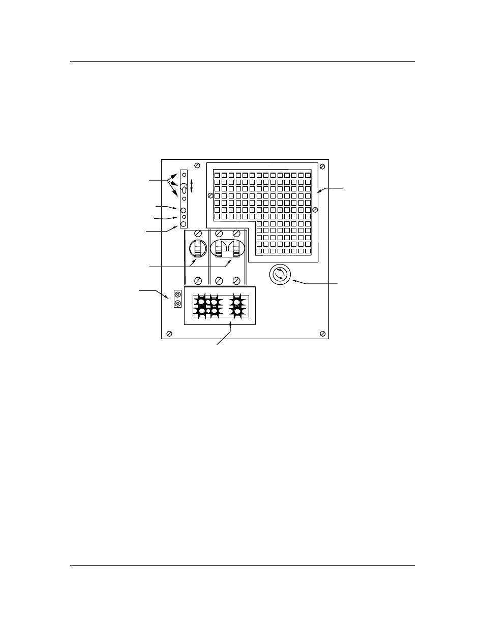
Figures 1 and 2 show the front and rear views of the fully equipped rectifier.
Figure 1 - NT5C06B/C Rectifier (front view)
Local float / equalize control
The rectifier is equipped with a momentary Float/Equalize switch. When the
switch is held in the EQL position, the rectifier changes to equalize mode
and boosts the output voltage to the value set by the EQL potentiometer.
Otherwise, the rectifier delivers a float voltage set by the FLT potentiometer.
Indicator lamps
Designation Color
Description
RFA/ON
Red
Rect. Failed or no load current *
Green
Rectifier
operational
Fan Red
Fan
Failed
LOAD
AC
F1
3/4A 250V
OUTPUT
V+
V-
DC
EQL
FLT
FAN
HVSD
ON/RFA
FILTER
OPTION
INRUSH
CURRENT
LIMIT
FUSE
CURRENT METER
TEST
POINTS
CIRCUIT
BREAKERS
EQUALIZE
/FLOAT
SWITCH AND
ADJUST
FAN ALARM
HVSD ADJUST
RECTIFIER
OK/FAIL
.