Avago Technologies Syncro CS 9271-8i User Manual
Page 13
LSI Corporation
- 13 -
Syncro CS 9271-8i Solution User Guide
October 2013
Chapter 2: Hardware and Software Setup
Syncro CS Cluster-in-a-Box Hardware Setup
4.
Place the Syncro CS controller on a flat, clean, static-free surface after grounding yourself.
NOTE
If you want to replace a bracket, refer to the Replacing Brackets on
MegaRAID SAS+SATA RAID Controllers Quick Installation Guide for
instructions.
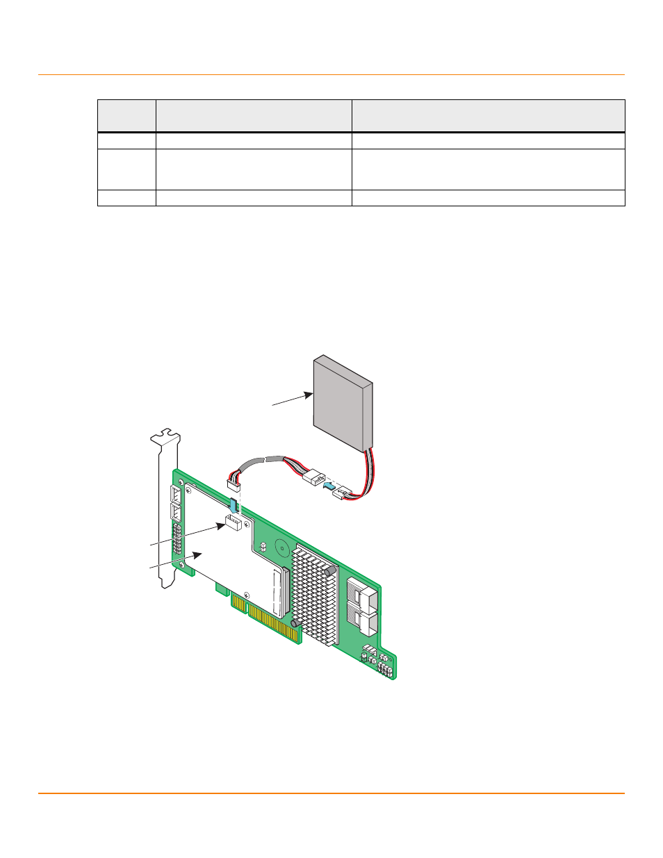
5.
Take the cable included with the kit and insert the smaller of the two 6-pin cable connectors on the cable into the
6-pin connector on the remote CVPM02 module, as shown in the following figure.
Figure 3 Connecting the Cable to the Remote CVPM02 Module
6.
Mount the CVPM02 module inside the CiB enclosure, based on the location and the type of mounting option.
J6B4
Onboard Serial UART connector
Reserved for LSI use.
J6B5
Global Drive Fault LED indicator
2-pin header
Connects to a single LED that indicates drive activity on
either port.
J6B6
Onboard Serial UART connector
Reserved for LSI use.
Table 1 Syncro CS 9271-8i Controller Jumpers and Connectors (Continued)
Jumper/
Connector
Type
Description
3_01851-00
J2B1
CVPM02
Module
CVFM02
Module