Scanner instruction manual, Analog output transmitter power supply, Interlock relay feature – Precision Digital PD6080 User Manual
Page 23
PD6080/PD6081 Super Snooper Modbus
Scanner Instruction Manual
23
4-20 mA Output Connections
Connections for the 4-20 mA transmitter output are made to the connector terminals labeled MA OUT.
The 4-20 mA output may be powered internally or from an external power supply.
12-35 VDC
Power
Supply
+
4-20 mA
Input Meter
-
+
R
I-
I+
1
3
2
RELAY1
3
2
1
24 V
-
4-20 mA Input
Remote Display,
Chart Recorder, Etc.
-
+
R
I-
I+
MA OUT
1
3
2
RELAY1
3
2
1
24 V
MA OUT
Figure 13. 4-20 mA Output Connections
Analog Output Transmitter Power Supply
The internal 24 VDC power supply powering the analog output may be used to power other devices, if the
analog output is not used. The I+ terminal is the +24 V and the R terminal is the return.
External Relay, Analog Output, & Digital I/O Connections
The relay, analog out, and digital I/O expansion modules PDA1004, PDA1011, and PDA1044 are
connected to the scanner using a CAT5 cable provided with each module. The two RJ45 connectors on
the I/O expansion modules are identical and interchangeable; they are used to connect additional
modules to the system. See LIM1044, Expansion Module Instruction Manual, for details.
Note: The jumper located between the RJ45 connectors of the PDA1044 must be removed on the second
digital I/O module in order for the system to recognize it as module #2.
Warning!
Do not connect or disconnect the expansion modules with the power on!
More detailed instructions are provided with each optional expansion
module.
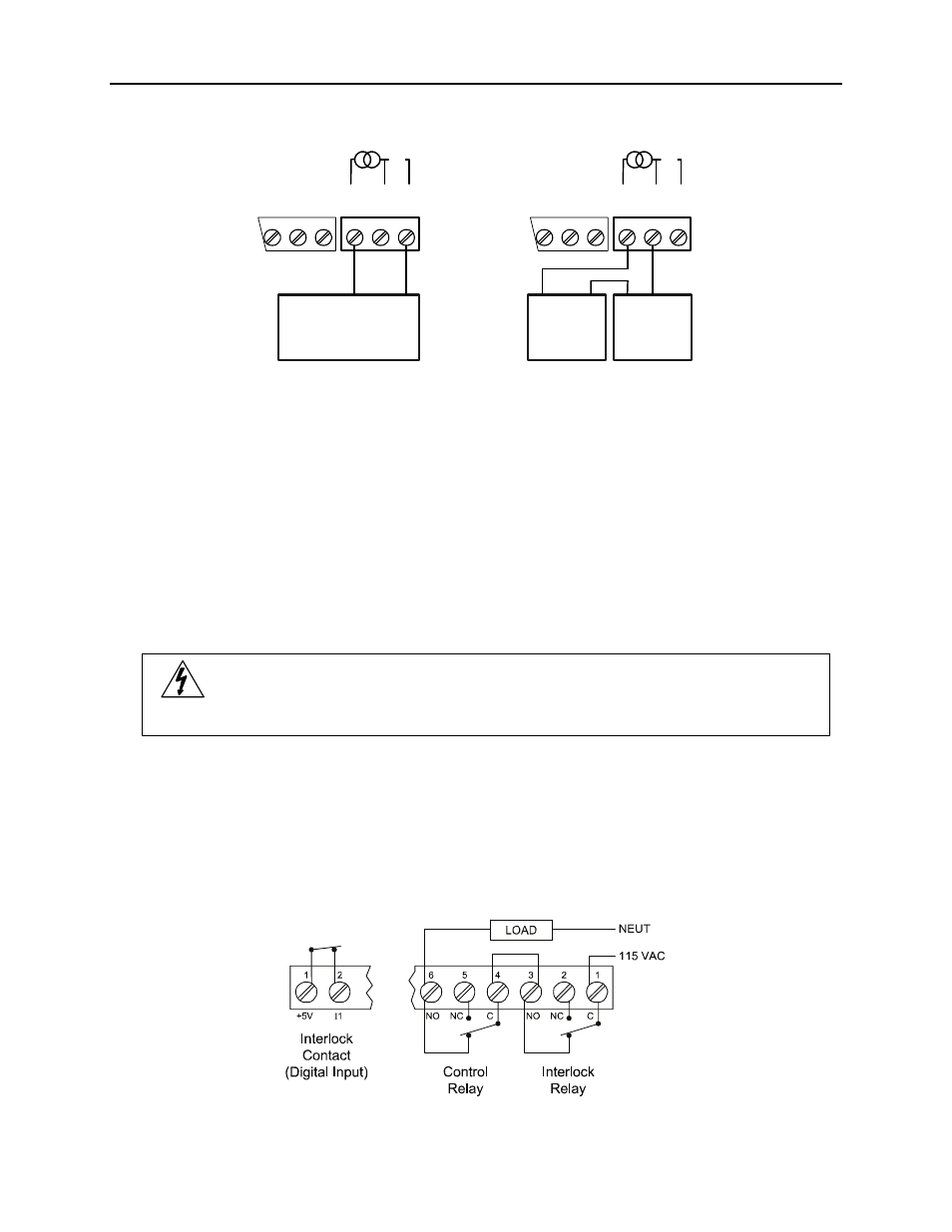
Interlock Relay Feature
As the name implies, the interlock relay feature reassigns one, or more, alarm/control relays for use as
interlock relay(s). Interlock contact(s) are wired to digital input(s) and trigger the interlock relay. This
feature is enabled by configuring the relay and relative digital input(s). In one example, dry interlock
contacts are connected in series to one digital input which will be used to force on (energize) the
assigned interlock power relay when all interlock contacts are closed (safe). The interlock relay front
panel LED flashes when locked out. The interlock relay would be wired in-series with the load (N/O
contact). See below.
Figure 14. Interlock Connections