Relay4 relay3, Relay2 relay1, Modbus rtu serial communications – Precision Digital PD6100 User Manual
Page 24: Relay connections, Ex+ ex- sg- sg
Model PD6100 Strain Gauge/Load Cell Meter Instruction Manual
24
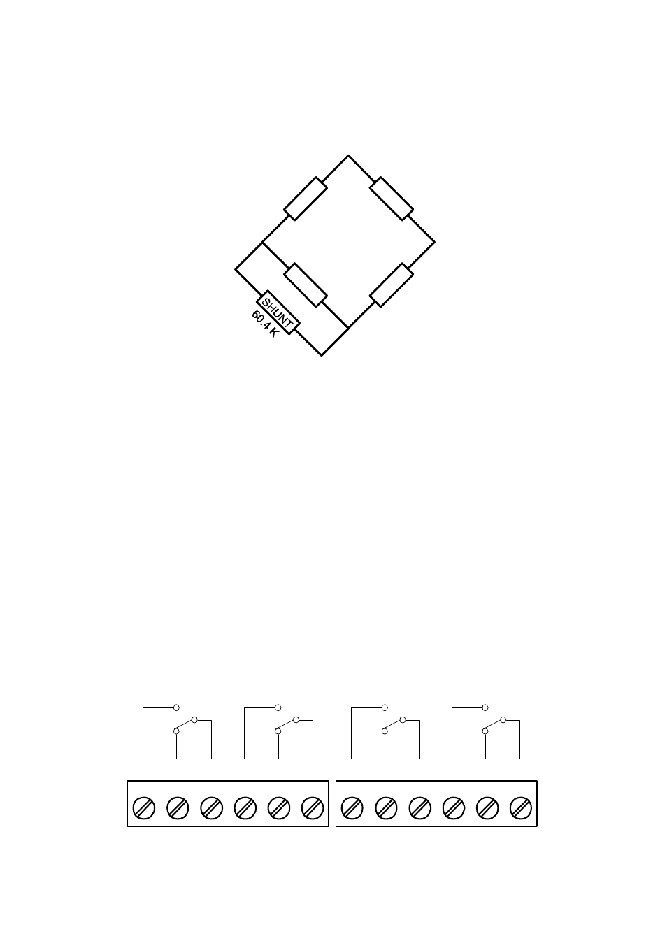
predetermined resistive load(60.4k). This technique can be used as a
means of verifying instrumentation by simulating a physical
input. With no load connected, the enabling of the shunt resistor
(switch 5) will simulate approximately a 70% F.S. load in the case of a
350Ω Strain Bridge.
Figure 13. Shunt Resistor
Modbus RTU Serial Communications
Serial communications connection is made to an RJ45 connector
labeled M-LINK on Figure 7. Use the PDA1232 for RS-232 interfacing,
the PDA8008 for USB interfacing, or the PDA1485 for RS-485
interfacing. The same port is used for interfacing with all expansion
modules (e.g. external relays, digital I/O).
Use the PDA1200 meter copy cable for meter-to-meter interfacing for
cloning purposes (i.e. copying settings from one meter to other meters).
Relay Connections
Relay connections are made to two six-terminal connectors labeled
RELAY1 – RELAY4 on Figure 7. Each relay’s C terminal is common
only to the normally open (NO) and normally closed (NC) contacts of the
corresponding relay. The relays’ C terminals should not be confused
with the COM (common) terminal of the INPUT SIGNAL connector.
Figure 14. Relay Connections
EX+
EX-
SG-
SG+
C
NO
NO
NC
NC
C
RELAY4
RELAY3
4
3
6
5
2
1
C
NO
NO
NC
NC
C
RELAY2
RELAY1
4
3
6
5
2
1