Ex+ ex- sg- sg – Precision Digital PD6100 User Manual
Page 22
Model PD6100 Strain Gauge/Load Cell Meter Instruction Manual
22
Shunt Resistor (Switch 5)
The PD6100 provides a means of simulating strain in a strain gauge
bridge circuit via a 60.4KΩ shunt resistor included in the meter. This will
simulate an approximate 70% full-scale load in the case of a 350Ω
strain bridge.
Switch
5
ON Shunt
Shunt resistor is
connected to the
input bridge.
Turn switch ON when you
want to simulate a strain
load
OFF Shunt
Shunt resistor is
disconnected from
the input bridge.
Turn this switch OFF to
remove the shunt resistor
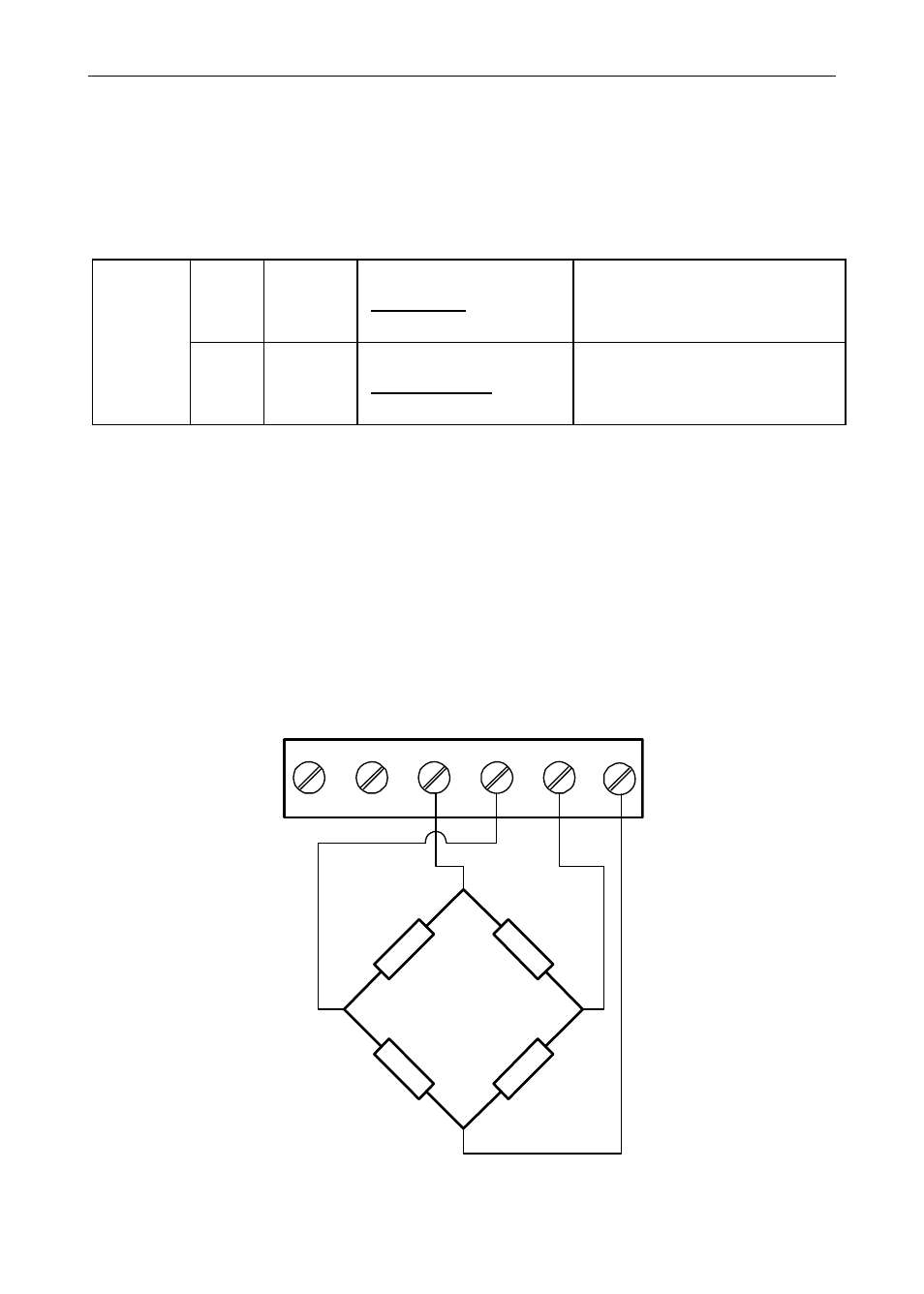
Strain Gauge Connections
The following figures show examples of strain gauge connections.
There is a 5-position DIP switch (CONFIG) to set up the input ranges and
ratiometric operation.
NOTE: Refer to Switch Configuration starting on page 20 for proper
configuration switch positioning.
Figure 10. Strain Gauge Powered by Internal Supply
EX+
COM
2
1
3
4
F4
SG+
SG-
INPUT SIGNAL
5
6
EX+
EX-
SG-
SG+
EX-