Sealey TA4000 User Manual
Page 20
20
■
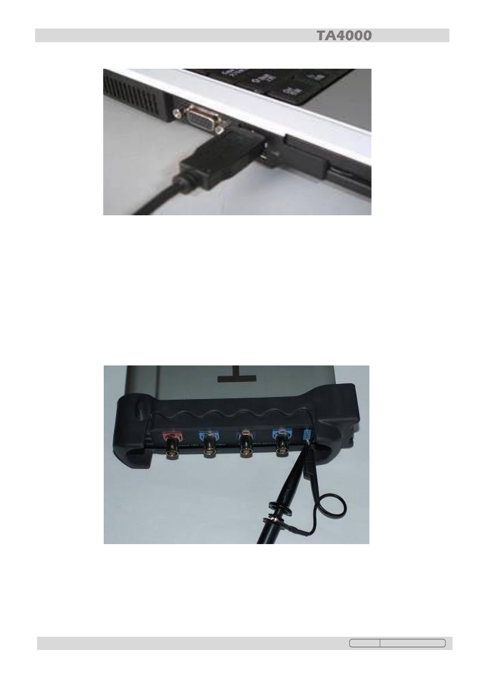
Input a signal to a channel of the oscilloscope
The oscilloscope is equipped with four channels plus external trigger.
Input a signal using the following steps:
1. Set the attenuation switch on the probe to 10x, and connect the probe lead to the CH1
BNC connector on the oscilloscope. Align the slots in the probe lead connector with the
pins on the BNC connector and push home. Rotate the outer ring clockwise to lock it.
Attach the tip of the probe and the ground clip to the Probe compensator Connector.
2. Set the CH1 probe attenuation of the oscilloscope to x10. (The default is x1).
Original Language Version
TA4000 Issue: 1 - 06/09/11
See also other documents in the category Sealey For the car:
- CPS02 (4 pages)
- PB397 (1 page)
- CPS03 (4 pages)
- CPS01 (8 pages)
- AK422 (1 page)
- VS9201 (1 page)
- TA111 (2 pages)
- TA125 (3 pages)
- TA130 (2 pages)
- PP100 (6 pages)
- PPLK (2 pages)
- PPVT (4 pages)
- PP7 (6 pages)
- TA050 (2 pages)
- TA126 (2 pages)
- TA131 (2 pages)
- VS207 (2 pages)
- TA303 (5 pages)
- MM18 (5 pages)
- TM103 (6 pages)
- TA320 (36 pages)
- MM20 (2 pages)
- MM405 (2 pages)
- BT101 (2 pages)
- TA101 (4 pages)
- BT101 (4 pages)
- BT101 (2 pages)
- BT101 (2 pages)
- BT101 (3 pages)
- BT101 (2 pages)
- BT101 (2 pages)
- BT101 (5 pages)
- TA200 (6 pages)
- TA201 (4 pages)
- TA202 (4 pages)
- TA300 (4 pages)
- TA203 (6 pages)
- TA302 (4 pages)
- TA330 (38 pages)
- TA311 (3 pages)
- TM103 (8 pages)
- TA304 (7 pages)
- TM102 (7 pages)
- VS2071 (2 pages)
- VS2072 (1 page)