4 transfer time, 5 battery temperature sensor operation, Operation 3.4 transfer time – Magnum Energy MS-PE Series User Manual
Page 41: Temperature compensation using bts
Page 34
©
2013 Magnum Energy, Inc.
Operation
3.4 Transfer
Time
While in Standby mode, the AC input is continually monitored. Whenever AC power falls below
the VAC dropout voltage (150 VAC, default setting), the inverter automatically transfers back to
Inverter mode with minimum interruption to your appliances—as long as the inverter is turned
on. The transfer from Standby mode to Inverter mode occurs in approximately 16 milliseconds.
While the MS-PE Series is not designed as a computer UPS system, this transfer time is usually
fast enough to hold them up. However, the VAC dropout setting has an effect on the ability of the
loads to transfer without resetting. The lower this setting, the longer the effective transfer will be
and therefore, the higher the probability for the output loads to reset. This occurs because the
incoming AC voltage is allowed to fall to a level that is so low that when the transfer does occur,
the voltage on the inverters output has already fallen to a level low enough to reset the loads.
The disadvantage of a higher VAC dropout setting is that smaller generators (or large generators
with an unstable output) may nuisance transfer. This commonly happens when powering loads that
are larger than the generator can handle—causing the generator’s output voltage to constantly
fall below the inverter’s input VAC dropout threshold.
Info: When switching from Inverter mode to Standby mode, the inverter waits
approximately 15 seconds to ensure the AC source is stable before transferring.
3.5 Battery Temperature Sensor Operation
The plug-in Battery Temperature Sensor (BTS) is used to determine the battery’s temperature.
This information allows the multi-stage battery charger to automatically adjust the battery charge
voltages for optimum charging performance and longer battery life.
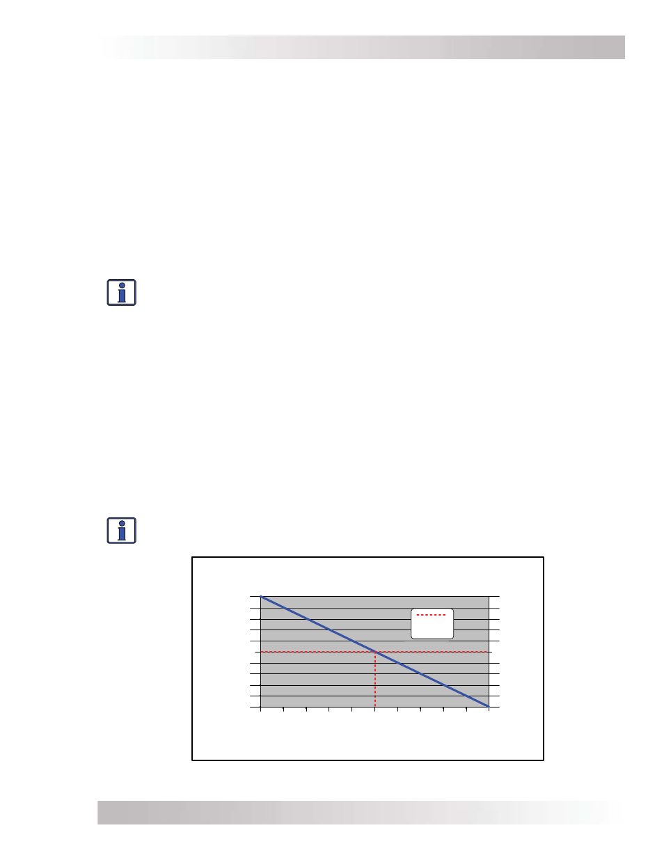
When the BTS is installed, if the temperature around the BTS is below 25°C (77°F) the absorb and
fl oat charge voltage increases, and if the temperature around the BTS is higher than 25°C (77°F),
the absorb and fl oat charge voltage decreases. See Figure 3-4
to determine how much the charge
voltage changes (increases or decreases) depending on the temperature reading of the BTS. For
example, the nominal absorb charge voltage for a fl ooded battery at 25°C (77°F) on a 24-volt
model is 29.2 VDC. If the battery temperature is 35°C (95°F), the absorb charge voltage would
decrease to 28.6 VDC (29.2 VDC - 0.6 change).
If the temperature sensor is NOT installed, the charge voltages will not be compensated and the
battery will maintain the charge it had at a temperature of 25°C (77°F). The life of the batteries
may be reduced if they are subjected to large temperature changes when the BTS is not installed.
Info: When the BTS is connected, the battery charger uses a value of 5mV/°C/Cell
from 0-50°C to change the charge voltage based on temperature.
-0.75
-0.6
-0.45
-0.3
-0.15
0
0.15
0.3
0.45
0.6
0.75
0
5
10
15
20
25
30
35
40
45
50
Temperature reading from BTS
Temperature Compensation using BTS
0C
32F
5C
41F
10C
50F
45C
113F
30C
86F
40C
104F
35C
95F
25C
77F
20C
68F
15C
59F
50C
122F
Change to battery charging voltage
no BTS
connected
24VDC units
+1.5V
+1.2V
+0.9V
+0.6V
+0.3V
No Change
-0.3V
-0.6V
-0.9V
-1.2V
-1.5V
48VDC units
+3.0V
+2.4V
+1.8V
+1.2V
+0.6V
No Change
-0.6V
-1.2V
-1.8V
-2.4V
-3.0V
Figure 3-4, BTS Temperature to Charge Voltage Change