Magnum Energy MS-PE Series User Manual
Page 11
Page 4
©
2013 Magnum Energy, Inc.
Introduction
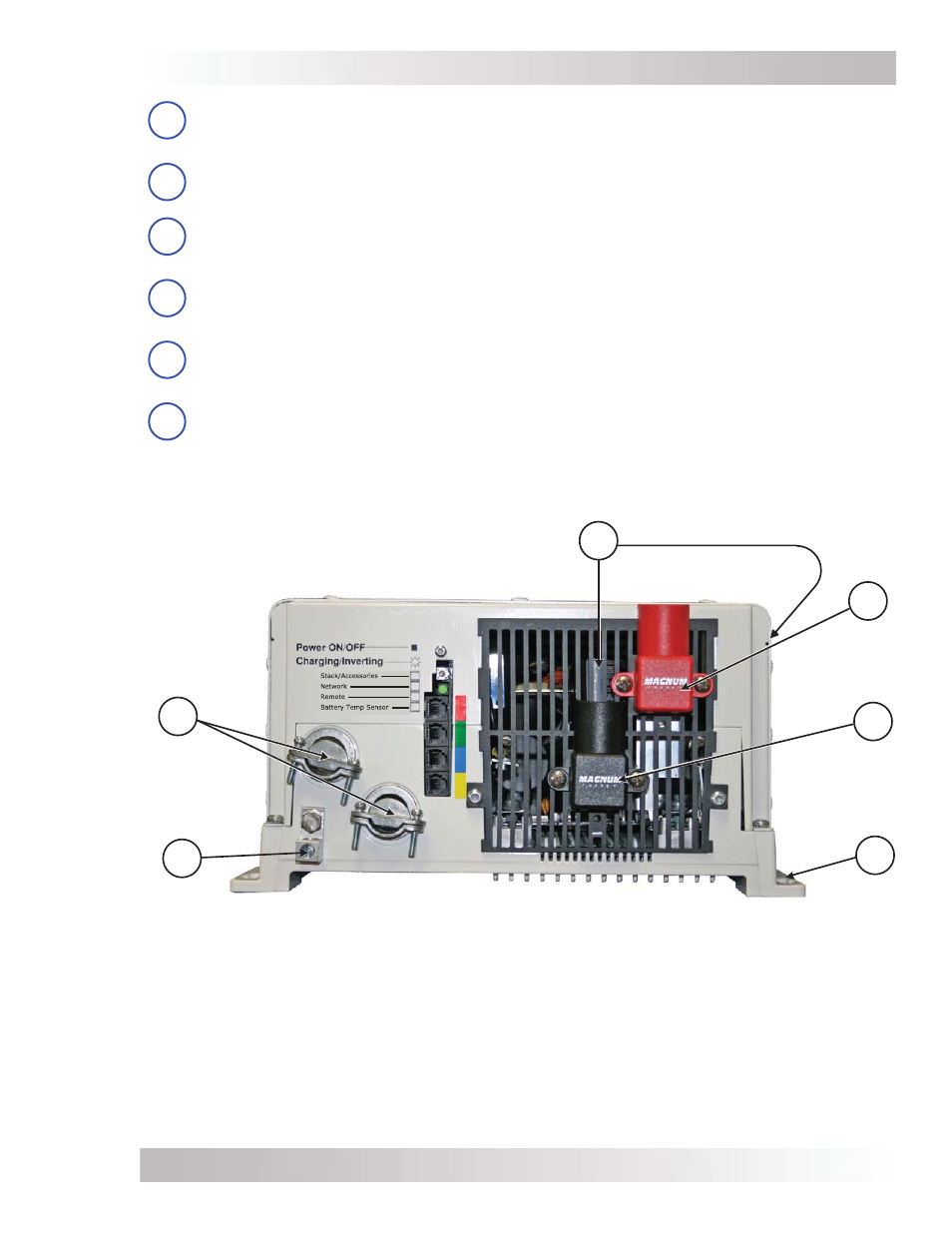
Figure 1-2, Electrical Connection Points
9
10
8
7
12
11
Positive (+)
DC Terminal
Negative (-)
DC Terminal
Mounting
Flange
DC Equipment
Ground Terminal
AC Entry/Exit
Connections
Intake Air Vents
(and on right side)
7
DC Equipment Ground Terminal – this connection is used to tie the exposed chassis
of the inverter to the DC grounding system. This terminal accepts CU/AL conductors from
2.1 to 33.6 mm
2
(#14 to #2 AWG).
8
AC Entry/Exit Connections – two 3/4” knockouts provided with cable-clamp
strain
relief
s to accommodate and secure the AC input and output
fi eld
wiring.
9
Intake Air Vents – ventilation openings to pull in air to help keep the inverter cool for
peak performance. The intake air vents are located on the front side and at the front on
the right side; see Figure 2-3 for the locations of the air vents.
10
Positive DC Terminal (red) – provides a 360 degree connection point for the positive
(+) cable from the battery bank; consists of a 5/16-18 x 5/8” bolt with a Kep or Flange
nut that holds the battery cable to the DC terminal.
11
Negative DC Terminal (black) – provides a 360 degree connection point for the negative
(-) cable from the battery bank; consists of a 5/16-18 x 5/8” bolt with a Kep or Flange
nut that holds the battery cable to the DC terminal.
12
Mounting Flange – used to secure the inverter to a shelf or to a wall.