Installation – Magnum Energy MS-PE Series User Manual
Page 34
©
2013 Magnum Energy, Inc.
Page 27
Installation
2.6.5
Neutral to Safety Ground Bonding
The recommended standards for safely wiring residential, commercial, and mobile installations
(e.g., caravans and boats) require that the neutral and safety ground be connected at the AC
source; whether it is the utility feed in your home, an inverter, or a generator. This is to establish
a specifi cation that maximizes the possibility that a circuit breaker will activate if a hot-wire-to-
ground fault occurs. These standards also require that the AC neutral be connected to safety ground
(often called a “bond”) in one, and only one, place at any time. The single bond is established in
order to make the electrical panel’s neutral line safe, by connecting it to ground. Without this bond,
the neutral can have up to
230 VAC with respect to ground. On the other hand, if more than one
bond is established, currents can circulate between neutral and ground and cause “ground-loop”
currents. These ground-loops can trip residential current devices (RCDs), cause an electric shock
hazard, and may be the reason for other annoying side effects.
In applications where you are using an inverter as one of your AC sources along with another
AC source (e.g., utility power or generator), there is the potential of having multiple connections
(bonds) between neutral and ground. Therefore, you must ensure that the inverter does not also
connect the neutral-to-ground while the other AC source is actively powering the inverter loads.
This can be prevented if your inverter is equipped with automatic neutral-to-ground switching.
WARNING: In most electrical systems, the neutral-to-ground bond is located in the
main utility service entrance panel. Remove any bond downstream from the inverter
to prevent multiple bonds. If there is an inverter sub-panel—separate from a main
electrical panel—it should have a removable wire that allows the neutral bus to be
unbonded from the ground busbar.
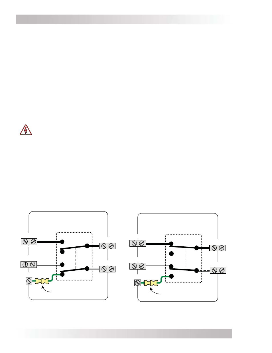
All MS-PE Series inverter/chargers have automatic neutral-to-ground switching to specifi cally work
in multiple source applications. The MS-PE Series inverters use an internal relay that automatically
connects the AC neutral output terminal to the vehicle/boat’s ground while inverting (Inverter
mode) to provide the neutral-to-ground bond; as shown in Figure 2-14. However, when an external
AC source (e.g., shorepower or a generator) is qualifi ed, another neutral-to-ground connection
is introduced in the system. When the MS-PE Series is connected to this external AC source and
goes into Standby mode, the internal relay automatically opens the neutral-to-ground connection,
as shown in Figure 2-15. This design keeps two neutral-to-ground connections from occurring at
the same time, thereby preventing an electrical shock hazard between the vehicle/boat’s neutral
and the external AC source’s neutral.
Figure 2-14, Neutral-to-Ground
Connection (Inverter Mode)
Figure 2-15, Neutral-to-Ground
Connection (Standby Mode)
Neutral
-to-Ground connection
(inside AC compartment)
GROUND
Neu-Gnd Relay (K1)
HOT IN
Inside MS-PE Series
Inverter
/Charger
(Inverter Mode)
NEUT OUT
NEUT IN
HOT OUT
Neutral
-to-Ground connection
(inside AC compartment)
GROUND
Neu-Gnd Relay (K1)
HOT IN
Inside MS-PE Series
Inverter
/Charger
(Standby Mode)
NEUT OUT
HOT OUT
NEUT IN