2 standby mode, 1 battery charging, Operation 3.2 standby mode – Magnum Energy MSH-M Series User Manual
Page 39
Page 30
©
2013 Magnum Energy, Inc.
Operation
3.2 Standby
Mode
The MSH-M Series features an internal battery charger and an automatic transfer relay when
operating in Standby mode. The Standby mode begins whenever AC power (shorepower or
generator) is connected to the inverter’s AC input. Once the AC voltage and frequency of the
incoming AC power is within the AC input limits, the AC transfer relay activates. This transfer
relay passes the incoming AC power through the inverter to power the AC loads on the inverter’s
output. This incoming power is also used to activate a powerful internal battery charger to keep
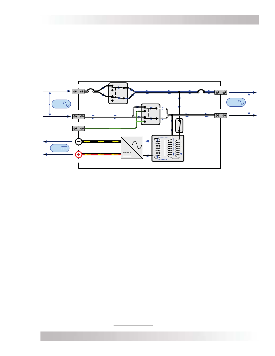
the battery bank charged in case of a power failure. Refer to Figure 3-2 to see the fl ow of power
from the AC input to the DC and AC output while in Standby mode.
AC
OUT
Neutral-Ground
Transfer Relay
AC Hot
Transfer Relay
HOT IN
NEUTRAL IN
AC GROUND
Power Transformer
FET Bridge
AC
DC
DC
OUT
HOT OUT
DC POSITIVE
DC NEGATIVE
NEUTRAL OUT
120
VAC
120
VAC
AC
IN
AC
Output
Relay
CB1
(60A)
CB2
(60A)
Figure 3-2, Power Flow – Standby Mode
3.2.1 Battery
Charging
The MSH-M Series is equipped with a PFC (Power Factor Corrected) and PI (Proportional-Integral)
multi-stage battery charger. The PFC feature controls the amount of power used to charge the
batteries to obtain a power factor as close as possible to 1 (or unity). This causes the battery charger
to look like a resistor to the line (forces the charge current wave shape to mirror the voltage wave
shape). The PI feature allows the charger voltage and current to change independently. These two
features maximize the real power available from the AC power source (i.e., shorepower or generator),
which translates into less power wasted and greater charging capabilities than most chargers today.
When an AC source is connected to the AC input, the inverter begins monitoring for acceptable
AC voltage. Once the AC voltage is accepted, the AC transfer relay closes. After the transfer relay
has closed, the inverter’s battery voltage is monitored to determine the charging stage. If the
battery voltage is low (≤12.8 VDC/12-volt models or ≤25.6 VDC/24-volt models), the charger
begins Bulk charging. If the DC voltage is high (>12.8 VDC/12-volt models or >25.6 VDC/ 24-volt
models), the charger will skip the Bulk and Absorb charge stages and go directly to Float charging.
However, if the incoming AC power is lost and returns within 2 minutes the charge mode returns
to the charge stage it was in prior to losing AC input—regardless of the battery voltage.
The MSH-M Series’ multi-stage charger can use up to fi ve different charging stages to help keep
the batteries healthy. The fi ve stages include an automatic 4-stage charging process (see Figure
3-3): Bulk, Absorb, Float, and Full Charge; and a manual Equalization (EQ) charge stage. The
automatic 4-stage charge process provides complete recharging and monitoring of the batteries
without damage due to overcharging. The EQ stage (requires a remote display to enable) is used
to stir up stratifi ed electrolyte and to reverse any battery plate sulfation that may have occurred.
While charging, the unit may go into charger back-off protection, which automatically reduces the
charge current to the batteries. This is caused by: 1) The internal temperature is too hot—the
charger automatically reduces the charge rate to maintain temperature; or 2) The AC input voltage
falls below 90 VAC—the charger will stop charging to help stabilize the incoming AC voltage.