2 mounting the inverter, Installation 2.2 mounting the inverter, Figure 2-2, approved mounting positions – Magnum Energy MSH-M Series User Manual
Page 18
©
2013 Magnum Energy, Inc.
Page 9
Installation
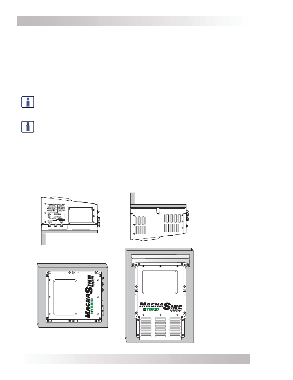
2.2 Mounting the Inverter
The inverter base can reach a temperature up to 90°C (194°F) and should be mounted on a
noncombustible surface*. This surface and the mounting hardware must also be capable of
supporting at least twice the weight of the inverter. To meet regulatory requirements, the MSH-M
Series must be mounted in one of the following positions (as shown in Figure 2-2):
• above or under a horizontal surface (shelf or table),
• on a vertical surface (wall) with the DC terminals to the right,
• on a vertical surface (wall) with the DC terminals toward the bottom, the MP-HOOD (inverter
hood) installed on the top, and either the ME-CB or MPX-CB conduit box installed on the
inverter’s bottom.
Info: The ME-CB or MPX-CB conduit box prevents material from falling out the bottom in
the event of an internal fi re, and also allow suffi cient ventilation to prevent the inverter
from overheating under normal operating conditions. The MP-HOOD helps prevent items
from falling inside—causing damage to the inverter.
Info: Magnum provides backplates for mounting the inverter. These backplates also allow
you to mount the MPX-CB conduit box (PN: BP-S single plate or BP-D, dual plate).
After determining the mounting position, refer to the physical dimensions as shown in Figure
2-3, or use the base of the inverter as a template to mark your mounting screw locations. After
marking the mounting screw locations, mount the unit with appropriate mounting hardware.
* Noncombustible surface – A surface made of material that will not ignite, burn, support combustion, or
release fl ammable vapors when subjected to fi re or heat as per the ASTM E136 standard. For the most part,
these are surfaces that are largely comprised of inorganic materials such as stone, steel, iron, brick, tile,
concrete, slate, and glass. Avoid common building materials such as gypsum board as well as any paint,
wall coverings, or wood.
Figure 2-2, Approved Mounting Positions
"WARNING- Risk of electrical shock. Use only the
ground-fault circuit-interrupter [receptacle(s) or
circuit breaker(s)] specified in the installation and
operation instructions manual supplied with the
inverter. Other types may fail to operate properly
when connected to this inverter equipment."
"CAUTION- To prevent fire, do not cover or obstruc
ventilation openings. Do not mount in zero-clearanc
compartment. Overheating may result."
"WARNING: MORE THAN ONE LIVE CIRCUIT.
SEE DIAGRAM."
"PROVIDED WITH I
NTEGRAL PROTECTION AGAIN
OVERLOADS."
30
60
60
S
HELF
OR
T
ABLE
M
OUNTED
(
RIGHT
SIDE
UP
)
S
HELF
OR
T
ABLE
M
OUNTED
(
UP
SIDE
DOWN
)
W
ALL
M
OUNTED
(DC
TERMINALS
TO
THE
RIGHT
)
W
ALL
M
OUNTED
(DC
TERMINALS
FACING
DOWN
*)
*W
HEN
THE
INVERTER
IS
MOUNTED
IN
THIS
POSITION
,
THE
MP-HOOD (
INVERTER
HOOD
ON
TOP
)
AND
EITHER
THE
ME-CB
OR
MPX-CB
(
CONDUIT
BOX
ON
BOTTOM
)
MUST
BE
USED
.