Installation, Figure 2-1, simplifi ed installation diagram, Ac transfer switch – Magnum Energy MSH-M Series User Manual
Page 16: Flux cap acitor ge nerator, On/off on/ off, Battery bank, Dc overcurrent protection (breaker or fuse/switch)
©
2013 Magnum Energy, Inc.
Page 7
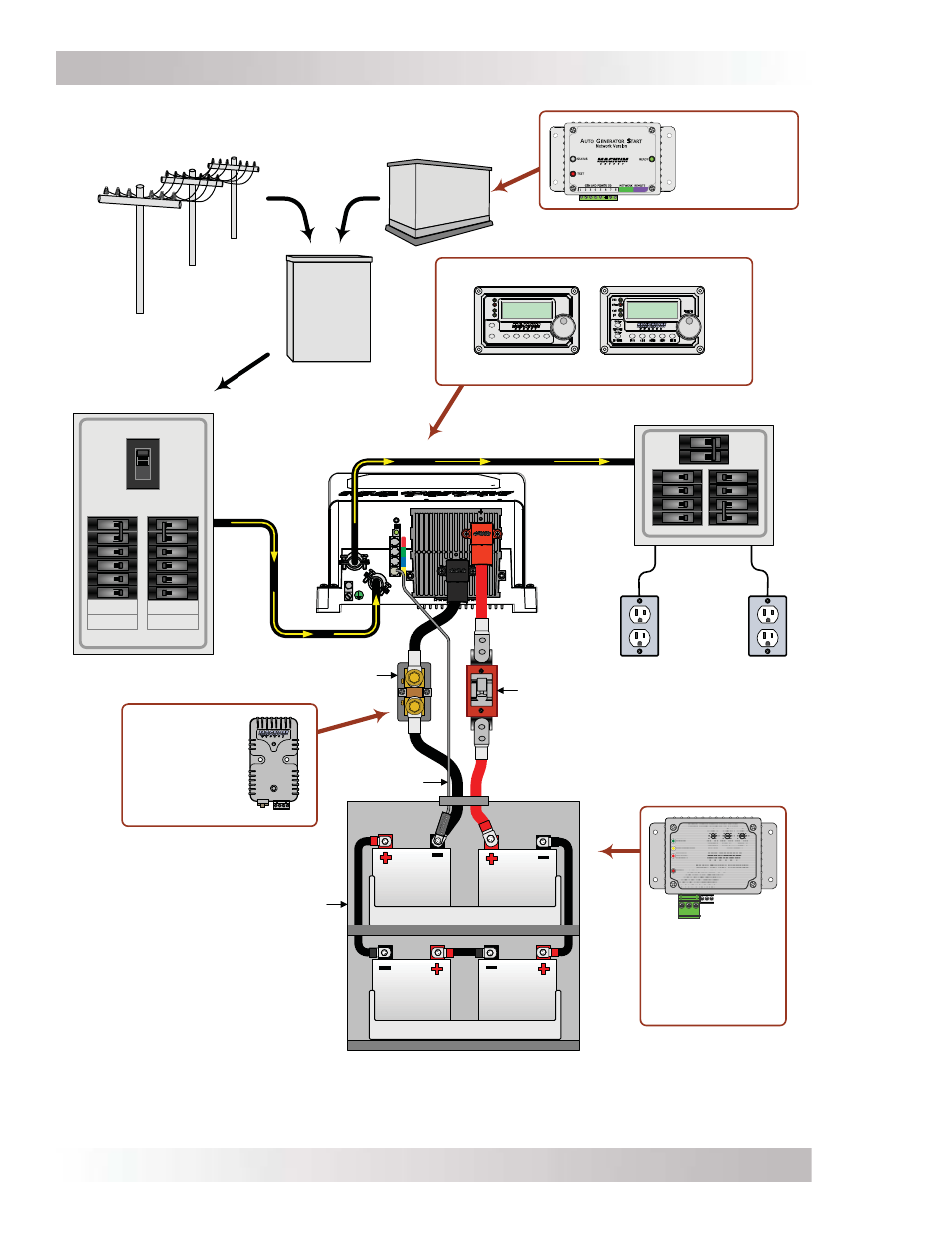
Installation
Figure 2-1, Simplifi ed Installation Diagram
Battery Bank
120VAC
power to
inverter
ON
OF
F
ON
OF
F
ON
OF
F
ON
OF
F
ON
OF
F
ON
OF
F
ON
OF
F
ON
OF
F
120
VAC
120
VAC
DC
Overcurrent
Protection
(breaker or
fuse/switch)
MSH-M
Series
Inverter/
Charger
Main Panel
Sub-Panel
120VAC inverter power
(or 120VAC pass-thru
power) to sub-panel
ME-BMK
Battery Monitor
with shunt
(Magnum
Accessory)
DC
Shunt
AC
Transfer
Switch
Generator Power
120VAC Output
Shorepower
120VAC Output
Flux Cap
acitor Ge
nerator
ON
OFF
ON
OF
F
ON
OF
F
ON
OF
F
ON
OF
F
ON
OF
F
ON
OFF
ON
OF
F
ON
OF
F
ON
OF
F
ON
OF
F
ON
OF
F
ON
OF
F
BTS
ON
OF
F
ON
OF
F
30
A
30
A
ME-SBC
Smart Battery
Combiner
(Magnum
Accessory)
ME-AGS-N
Auto Gen Start
Controller
(Magnum
Accessory)
SELECT
TECH
AGS
METER
SETUP
SHORE
INVERTE
R
CHARGER
INV
CHG
FAULT
PWR
ON/OFF
ON/
OFF
Remote Controls (Magnum Accessories)
ME-RC50
ME-ARC50