Magnum Energy MSH-M Series User Manual
Page 14
©
2013 Magnum Energy, Inc.
Page 5
Introduction
CB2 (60A)
AC Output
17
CB1 (60A)
AC Input
16
15 AC Access Cover
14 Model/Serial
Number Label
13
Exhaust Air
Vents
(and on
right side
– rear)
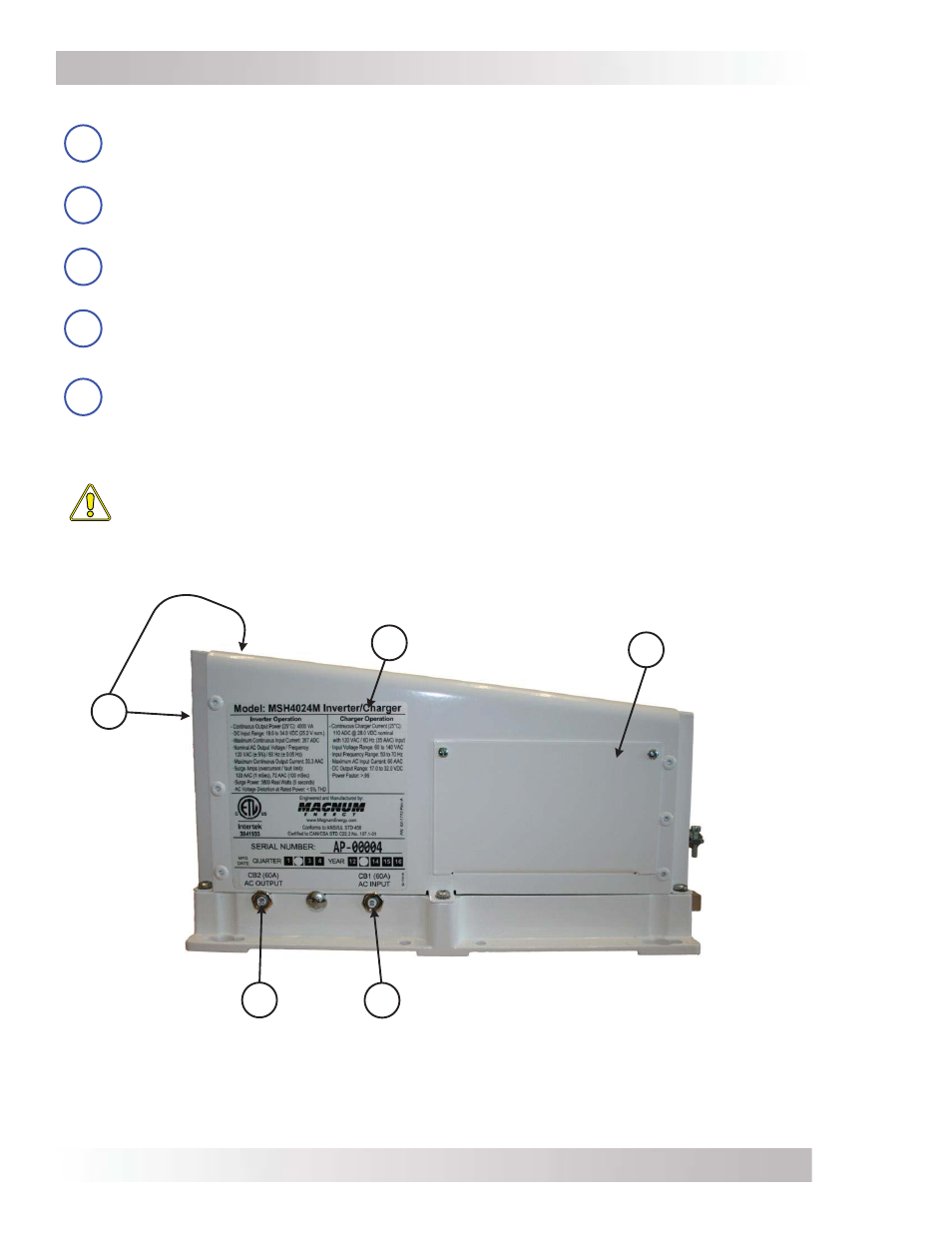
Figure 1-3, Left Side Features
The left side of the MSH-M Series inverter is equipped with the following features (Figure 1-3):
13
Exhaust Air Vents – ventilation openings that allow heated air to be removed by the
internal cooling fan. The exhaust air vents are located on the back side and at the rear
on the right side; also see Figure 2-3 for the location of the air vents.
14
Model/Serial Number Label – includes model/serial number information, date of
manufacture, and inverter and charger specifi cations. See the MSH-M specifi cations in
Appendix A for more information and a list of available models.
15
AC Access Cover – provides access to the internal AC wiring terminal block (see Figure
2-8). This terminal block is used to hardwire all inverter AC input and output wiring
connections. Remove the two screws to access the AC wiring terminal block.
16
AC Input Circuit Breaker (CB1) – this 60-amp AC circuit breaker protects the unit’s
internal charger wiring and pass-thru relay while in Standby mode. This circuit breaker
pops out when it opens—press in to reset.
17
AC Output Circuit Breaker (CB2) – this 60-amp AC circuit breaker protects the output
wiring inside the inverter while load supporting during Standby mode. This output circuit
breaker is not branch-rated, therefore any loads connected to the inverter’s output must
be protected by an external (NEUTRAL and HOT) branch-rated circuit breaker. This circuit
breaker pops out when it opens—press in to reset.
CAUTION: The inverter’s internal AC transfer relays are rated for 60 amps. The pass-
thru current must be no greater than 60 amps or damage to the relays may occur.