6 grounding inverters, Installation, Figure 2-10, grounding system for msh-m series – Magnum Energy MSH-M Series User Manual
Page 32: Dc e, Ac e
©
2013 Magnum Energy, Inc.
Page 23
Installation
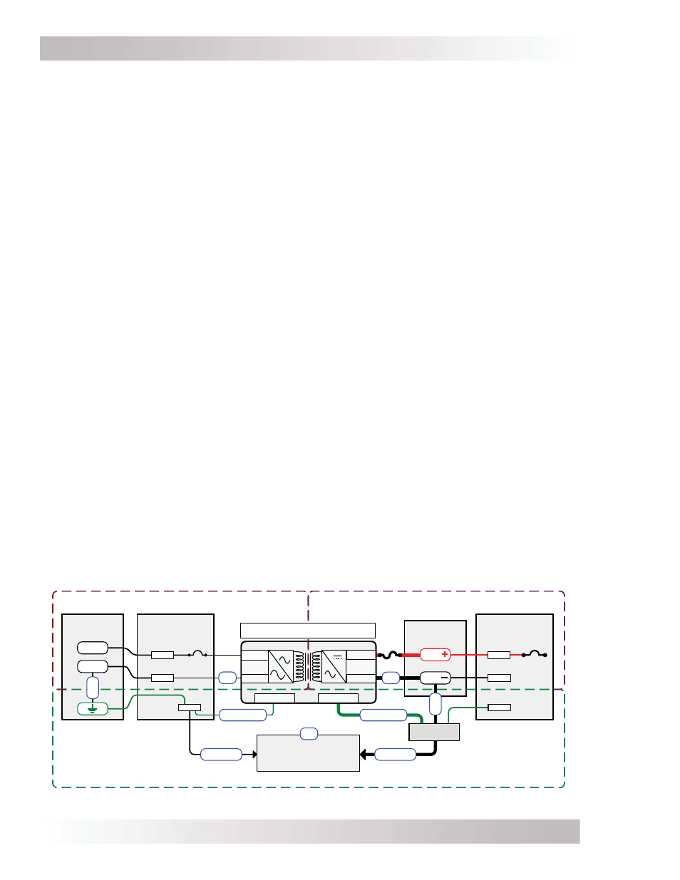
Figure 2-10, Grounding System for MSH-M Series
AC S
OURCE
(
SHOREPOWER
)
AC S
ERVICE
P
ANEL
Neutral
AC
Ground
Hot
DC S
ERVICE
P
ANEL
DC
Ground
DC S
OURCE
(
BATTERY
)
AC
DC E
LECTRICAL
S
YSTEM
AC E
LECTRICAL
S
YSTEM
Positive
Negative
DC
G
ROUNDING
S
YSTEM
AC Ground
DC Ground
Hot
BAT
Positive
BUSBAR
Neutral
BUSBAR
BUSBAR
BUSBAR
Negative
BUSBAR
BUSBAR
BAT
SBJ
GC
GC
EGC - AC
EGC - DC
GEC-AC
GEC-DC
DC SYSTEM
GROUND BUSBAR
G
ROUNDING
E
LECTRODE
(Vehicle chassis/frame
or main engine frame)
MSH-M Series Inverter/Charger
GE
NEUT
HOT
SBJ
2.6 Grounding
Inverters
The MSH-M Series
inverter/charger uses both AC and DC electrical systems, therefore each electrical
system is required to be properly connected to a permanent, common “ground” reference. An
inverter that is properly grounded limits the risk of electrical shock, reduces radio frequency noise,
and minimizes excessive surge voltages induced by lightning. The installation must ensure there is
a well-defi ned, very
low resistance path from the electrical system to the grounding system. The
low resistance path helps stabilize the electrical system voltage with respect to ground and carries
fault currents directly to ground, causing a fuse to blow or a circuit breaker to trip if the electrical
system malfunctions (i.e., short circuits).
To understand how the conductors in the electrical circuit
will be connected to the system ground, review the following terms along with Figure 2-10:
• Grounded
Conductor
(GC): The wire in the electrical system that normally carries current (i.e.,
AC neutral and DC negative), and is intentionally connected or “bonded” to the ground system.
This wire, or the ends of this wire, should be colored white or gray.
• Equipment Grounding Conductor (EGC): A wire that does not normally carry current and is
used to connect the exposed metal parts of equipment—that might be accidentally energized—
to the grounding electrode or to the grounded conductor.
• Grounding Electrode Conductor (GEC): The wire that does not normally carry current and
connects the grounded conductor and/or the equipment grounding conductor to the common
ground reference, usually at the ground busbar in the service equipment.
• Grounding
Electrode
(GE): A conducting element that establishes an electrical connection for
a common ground reference. In vehicles, it is usually the chassis or frame; in vessels, it is the
largest metal item onboard, usually the main engine frame.
• System Bonding Jumper (SBJ): The connection or “bond” between the grounded conductor
in the electrical system (AC neutral/DC negative) and the equipment grounding conductor.
For proper grounding, each electrical system must connect all exposed metal parts of equipment
(via Equipment Grounding Conductors – EGC) and one of the current-carrying conductors
(Grounded Conductor – GC) together at a common point (ground busbar), usually by a System
Bonding Jumper (SBJ). The common point of each electrical system is then connected (via
Grounding Electrode Conductor – GEC) to the Grounding Electrode (GE). The connection to the
grounding electrode should be made at one and only one point in each electrical system (AC
and DC); otherwise, parallel paths will exist for the currents to fl ow. These parallel current paths
would represent a safety hazard and are not allowed in installations wired per the NEC/CEC.
Since the MSH-M Series uses both AC and DC power—to prevent parallel current paths—the AC
electrical system is isolated from the DC electrical system by an internal transformer.