Figure 5.4, External setpoint analog signal – Yaskawa iQpump Controller User Manual User Manual
Page 93
5.1 iQpump Drive Basic Programming Parameters
YASKAWA TM.iQp.06 iQpump Controller User Manual
93
Figure 5.3
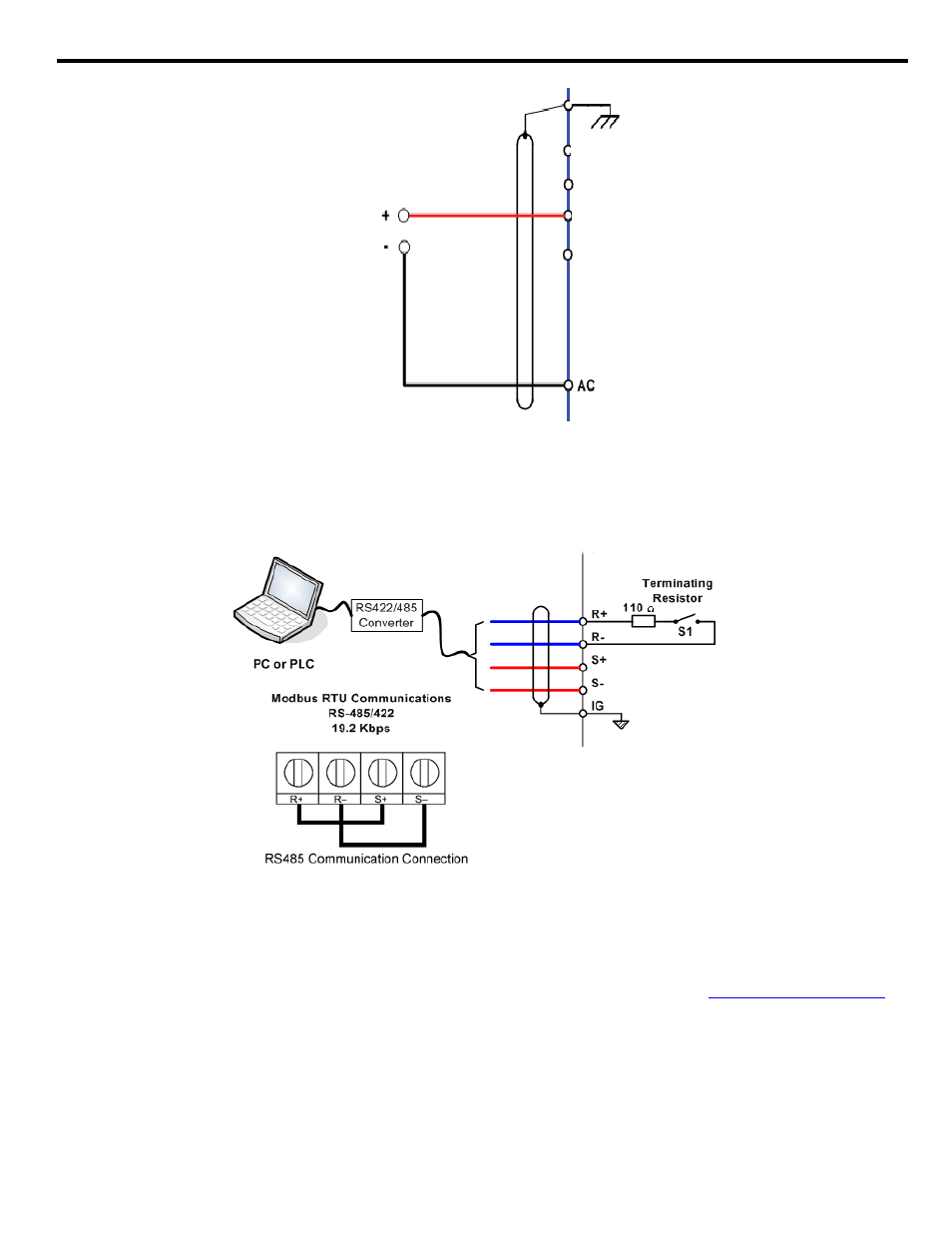
Figure 5.4 External Analog Signal Setpoint Reference
If you want the iQpump drive to receive the “Auto Setpoint” from serial communication: Set b1-01 = “2: Serial Com,” and connect
the RS-485 / 422 serial communications cable to terminals R+, R-, S+, and S- on the control I/O terminal block.
Refer to
for the connection diagram using a PC to provide the auto setpoint reference to the iQpump drive. Further information
regarding Modbus address and communication protocols
Refer to Parameters on page 165
and Appendix: D .
Figure 5.4
Figure 5.5 Connection Diagram of PC or PLC
If you want the iQpump drive to receive the “Auto Setpoint” for a network communication option card: Set b1-01 = “3: Option
PCB”, and plug a network option board (p/n SI-J) into the 2CN port on the iQpump drive Control PCB. Consult the manual supplied with
the option board for instructions on integrating the iQpump drive into the network system.
The iQpump drive can support the following network communication options. Refer to the appropriate Installation Guide (IG) and
Technical Manual (TM) for further details. These network communications documents can be located at
http://iQpump.yaskawa.com
.
• Profibus DP Option Card CM061
Manual: IG.AFD.12
• DeviceNet Option Card CM05X
Manual: IG.AFD.14
• Modbus Plus Option Card CM071
Manual: IG.AFD.17
• Modbus TCP / IP Option Card CM090
Manual: IG.AFD.25
• EtherNet / IP Option Card CM092
Manual: IG.AFD.26
External Setpoint
Analog Signal
+V +15 Vdc +/- 10 %, 20 mA
A1 0 to +/- 10 Vdc, 20 kΩ
Ω*
E (G)