Yaskawa iQpump Controller User Manual User Manual
Page 171
YASKAWA
TM.iQp.06 iQpump Controller User Manual
171
E1-04
0303
Maximum Output
Frequency
Max Frequency
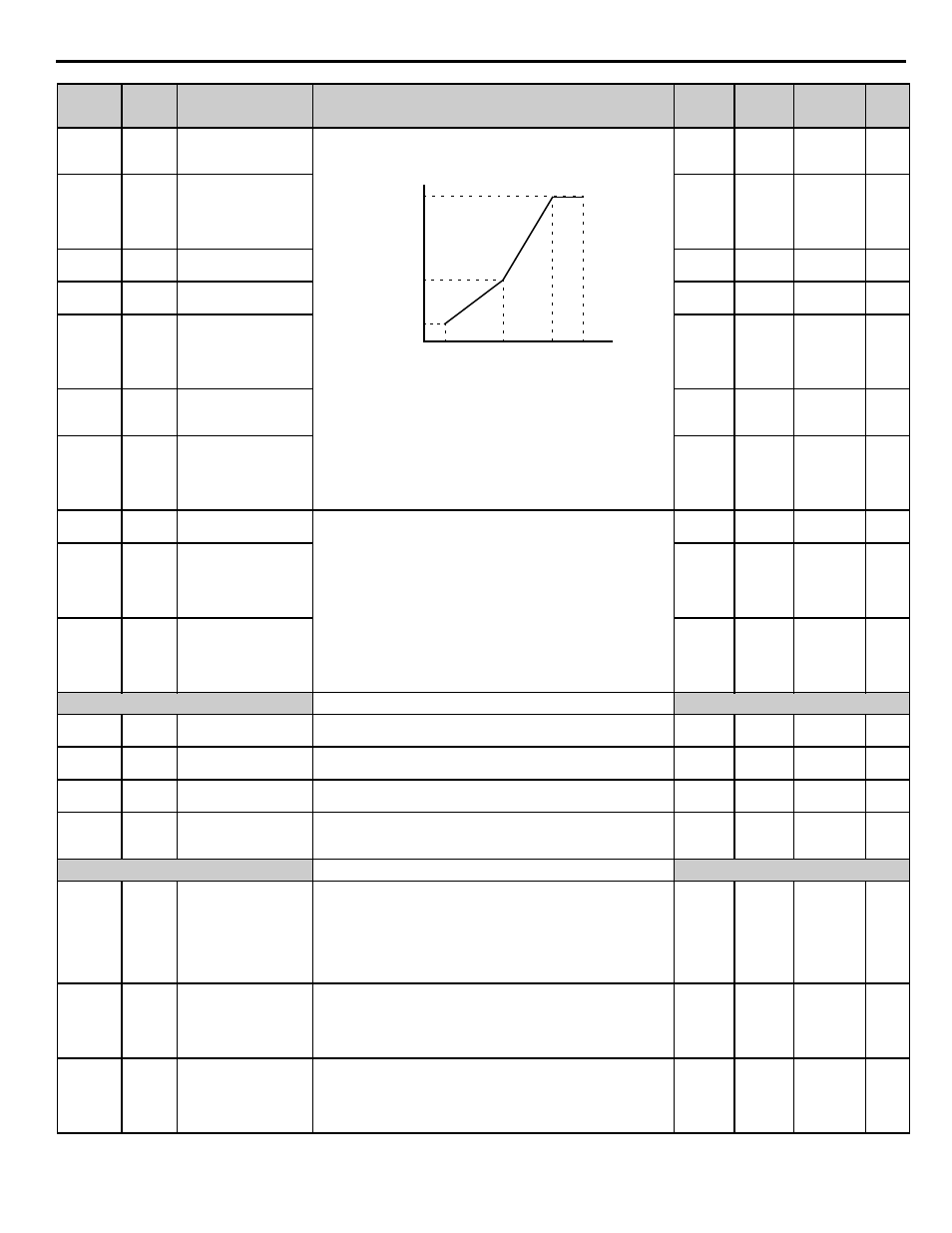
To set V/f characteristics in a straight line, set the same values for E1-07
and E1-09. In this case, the setting for E1-08 will be disregarded.
Always ensure that the four frequencies are set in the following manner:
E1-04 (FMAX) E1-06 (FA) > E1-07 (FB) E1-09 (FMIN)
0.0 ~
120.0 Hz
60.0 Hz Programming
E1-05
0304
Maximum Output
Voltage
Max Voltage
0.0 ~ 255.0
(240V)
0.0 to
510.0
(480V)
230.0 V
460.0 V
Programming
E1-06
0305
Base Frequency
Base Frequency
0.0 ~
200.0 Hz
60.0 Hz Programming
E1-07
0306
Mid Output Frequency A
Mid Frequency A
0.0 ~
200.0 Hz
3.0 Hz
Programming
E1-08
0307
Mid Output Voltage A
Mid Voltage A
0.0 ~ 255.0
(240V)
0.0 to
510.0
(480V)
17.2 Vac
34.5 Vac Programming
E1-09
0308
Minimum Output
Frequency
Min Frequency
0.0 ~
200.0 Hz
1.5 Hz
Programming
E1-10
0309
Mid Output Voltage
Min Voltage
0.0 ~ 255.0
(240V)
0.0 to
510.0
(480V)
10.3 Vac
20.7 Vac Programming
E1-11
030A
Mid Output Frequency B
Mid Frequency B
Set only when V/f is finely adjusted at rated output range.
Adjustment is not normally required.
0.0 ~
200.0 Hz
0.0 Hz
Programming
E1-12
030B
Mid Output Voltage B
Mid Voltage B
0.0 ~ 255.0
(240V)
0.0 to
510.0
(480V)
0.0 Vac Programming
E1-13
030C
Base Voltage
Base Voltage
0.0 ~ 255.0
(240V)
0.0 to
510.0
(480V)
0.0 Vac Programming
Motor Setup
E2-01
030E
Motor Rated Current
Motor Rated FLA
Set to the motor nameplate full load amps.
10 ~
200 %
kVA
Dependent
Pump Quick
Setup
E2-03
030F
No-Load Current
Sets the magnetizing current of the motor.
kVA
Dependent
kVA
Dependent Programming
E2-04
0311
Number of Motor Poles
Number of Poles
Set to the number of poles. Used for no-flow detection function and for
the calculation of rpm related parameters.
2 ~ 48
2
Pump Quick
Setup
E2-05
0312
Motor Line-to-Line
Resistance
Term Resistance
Phase to phase motor resistance, normally set by the autotuning
routine.
0.000 ~
65.000
kVA
Dependent
Programming
—
Communication Option Setup
F6-01
03A2
Operation Selection after
Communication Error
Com Bus Flt Sel
Sets the stopping method for option PCB communications error (BUS
fault). Active only when a communications option PCB is installed and
when b1-01 or b1-02 = 3.
0: Ramp to Stop
1: Coast to Stop
2: Fast-Stop
3: Alarm Only
0 ~ 3
1
Programming
—
F6-02
03A3
Input Level of External
Fault from
Communication Option
Card
EF0 Detection
0: Always detected
1: Detected only during run
0 ~ 1
0
Programming
—
F6-03
03A4
Stopping Method for
External Fault from
Communication Option
Card
EF0 Fault Action
0: Ramp to Stop
1: Coast to Stop
2: Fast-Stop
3: Alarm Only
0 ~ 3
1
Programming
—
Parameter
No.
Addr.
Hex
Parameter Name
Digital Operator
Display
Description
Setting
Range
Factory
Setting
Menu
Location
Page
No.
Output voltage (V)
Frequency (Hz)
FMIN FA FBASE FMAX
(E1-09) (E1-07) (E1-06) (E1-04)
VMAX
(E1-05)
VBASE
(E1-13)
VA
(E1-08)
VMIN
(E1-10)