Master, Master node node al on e al on e, Setting the iqpump drive networking parameters – Yaskawa iQpump Controller User Manual User Manual
Page 253: Verifying the iqpump drive network communications

G.9 iQpump Software Multiplexing Set-up
YASKAWA
TM.iQp.06 iQpump Controller User Manual
253
2.
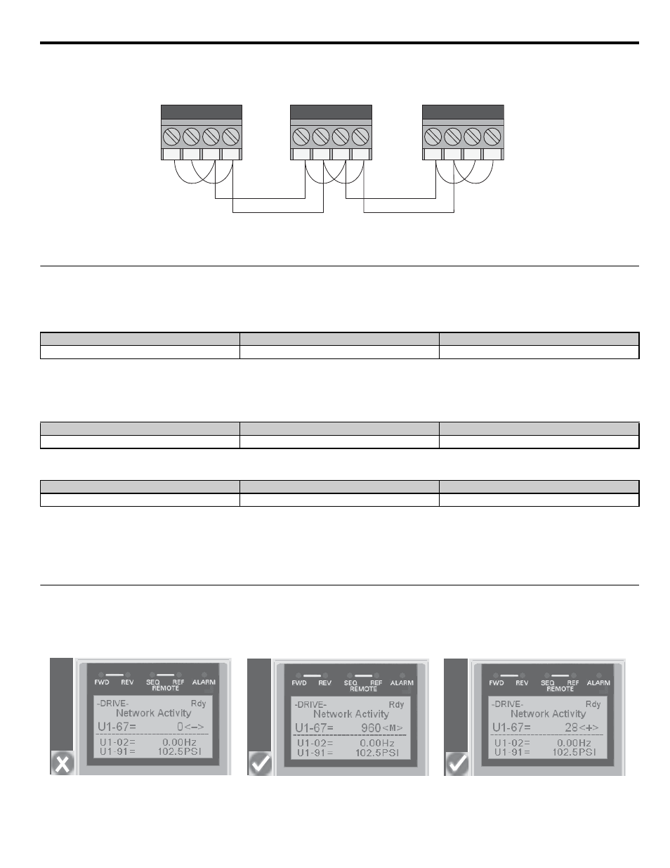
Use shielded communication cable for steps 3 and 4 to connect the iQpump drives in a daisy chain manner according to Figure G.12.
3.
Daisy chain the (R+ to S+) terminals between each iQpump drive.
4.
Daisy chain the (R- to S-) terminals between each iQpump drive.
Figure G.10
Figure G.12
◆ Setting the iQpump Drive Networking Parameters
1.
Set parameter H5-01, Serial Node Address, on each iQpump drive.
Note:
For optimal performance, use consecutive numbers starting from 1. Parameter setting H5-01 must be unique for each
iQpump drive.
2.
Set parameter P9-25, Highest Node Adr, on each iQpump drive.
Note:
For optimal performance, set to highest H5-01 value. This setting must be the same for all the iQpump drives on the
network.
3.
Set P1-01 to 3 (MEMOBUS/Modbus Network) on all the iQpump drives.
4.
Cycle main power to all networked iQpump drives.
Note:
The H5-01 setting will not take effect until power is cycled to the iQpump drive and may cause communication errors
and unexpected behavior.
◆ Verifying the iQpump Drive Network Communications
Access monitor U1-67, Network Activity, and verify that:
•
No iQpump drives have a value of 0 <->
• All iQpump drives are receiving valid data indicated by a regular change in the monitor value.
•
At least one iQpump drive has the unit
Figure G.11
Figure G.13 Example Digital Operator Displays for Verifying Correct Communication
Drive 1
Drive 2
Drive 3
H5-01 = 1
H5-01 = 2
H5-01 = 3
Drive 1
Drive 2
Drive 3
P9-25 = 3
P9-25 = 3
P9-25 = 3
Drive 1
Drive 2
Drive 3
P1-01 = 3
P1-01 = 3
P1-01 = 3
R+
S+
R-
S-
Drive 3
R+
S+
R-
S-
Drive 2
R+
S +
R-
S-
Drive 1
Master
Master
Node
Node
Al
on
e
Al
on
e
