Table 2.10, For c, Shunt connector cn15 – Yaskawa iQpump Controller User Manual User Manual
Page 49
2.3 Control Wiring
YASKAWA TM.iQp.06 iQpump Controller User Manual
49
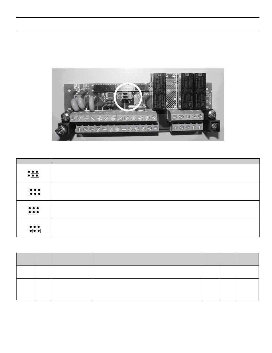
◆ Shunt Connector CN15
The shunt connector CN15 is described in this section. The shunt connector along with parameters H4-07 and H4-08 select the signal
range of the analog output terminals FM and AM.
Shunt connector CN15 is only available when the optional Terminal Card with the 4-20 mA Analog Output Monitor is installed (Model
No. ETC618120). See
, for installation of the optional Terminal Card.
The function of various shunt connector CN15 configurations is shown in
.
Figure 2.5 Shunt Connector CN15 Location
Table 2.10 Shunt Connector CN15 Configuration Options
The software configuration for the analog output monitor signal type is listed below:
CN15
Analog Output Monitor Configurations
Voltage Output (0 - 10 Vdc) for terminals FM-AC (CH1) and AM-AC (CH2)
Current Output (4 ~ 20 mA) for terminals FM-AC (CH1) and AM-AC (CH2)
Voltage Output (0 - 10 Vdc) for terminals FM-AC (CH1)
Current Output (4 ~! 20 mA) for terminals AM-AC (CH2)
Current Output (4 ~ 20 mA) for terminals FM-AC (CH1)
Voltage Output (0 - 10 Vdc) for terminals AM-AC (CH2)
Parameter
No.
Addr.
Hex
Parameter Name
Digital Operator
Display
Description
Setting
Range
Factory
Setting
Menu
Location
H4-07
0423
Terminal FM Signal Level
Selection
AO Level Select1
0: 0 - 10 Vdc
2: 4 ~ 20 mA*
0 or 2
0
Programming
H4-08
0424
Terminal AM Signal Level
Selection
AO Level Select2
0: 0 - 10 Vdc
2: 4 ~ 20 mA*
* An analog output of 4 ~ 20 mA cannot be used with the standard terminal
board. Therefore an optional terminal board (with shunt connector CN15)
is needed.
0 or 2
0
Programming