Application examples, Simple duplex system, G.9 iqpump software multiplexing set-up – Yaskawa iQpump Controller User Manual User Manual
Page 258: Figure g.15 simplified wiring diagram
258
YASKAWA
TM.iQp.06 iQpump Controller User Manual
G.9 iQpump Software Multiplexing Set-up
◆ Application Examples
■
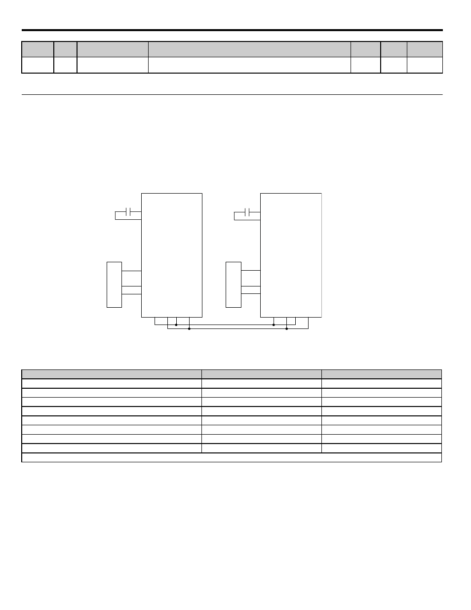
Simple Duplex System
A customer requires a duplex system with the following capabilities:
•
Control the system pressure using 2 iQpump drives (no PLCs).
• Alternate iQpump drives everyday to even out the pump wear.
• Toggle switch for Run command.
•
Each iQpump drive will have its own feedback transducer and because of shut-off valves, the network feedback as a back-up should not be used.
•
Pump is at optimal running speed when running at fixed speed is 54.0 Hz.
•
Setpoint is 100 psi, feedback scale is 145 psi, start level is 80 psi.
Figure G.13
Figure G.15 Simplified Wiring Diagram
Related Parameters for Simple Duplex System Example
P9-29
089C
Net Start Delay
Net Start Delay
After the first drive on the network has been put on Auto mode, the network will
wait this amount of time before selecting and starting the Lead Drive.
0.0 ~
60.0 s
2.0 s
Programming
Description
Drive A
Drive B
Run Source: 1 = Terminals
b1-02 = 1
b1-02 = 1
Node Address
H5-01 = 1
H5-01 = 2
Highest Node Address
P9-25 = 2
P9-25 = 2
Pump Mode: 3 = Network
P1-01 = 3
P1-01 = 3
Feedback Source: 0 = Analog
P9-02 = 0
P9-02 = 0
Lag Fixed Speed
P9-06 = 54.0 Hz
P9-06 = 54.0 Hz
Setpoint
U1-01 = 100 psi
U1-01 = 100 psi
Start Level
P1-04 = 80 psi
P1-04 = 80 psi
* All other multiplexing and alternation parameters are at default settings.
Parameter
No.
Addr.
Hex
Parameter Name
Digital Operator Display
Description
Setting
Range
Factory
Setting
Menu
Location
Drive A
CIMR-P7U40111-107
R+
S+
S-
R-
A2
AC
+V
A1
SN
S1
PRESSURE FEEDBACK
A
Drive B
CIMR-P7U40111-107
R+
S+
S-
R-
A2
AC
+V
A1
SN
S1
PRESSURE FEEDBACK B
RUN
RUN