D.1 using modbus communication, Using modbus communication, Modbus communication configuration – Yaskawa iQpump Controller User Manual User Manual
Page 214: Communication specifications, Communication connection terminal
214
YASKAWA
TM.iQp.06 iQpump Controller User Manual
D.1 Using Modbus Communication
D.1 Using Modbus Communication
Serial communication can be performed with Direct Digital Controllers (DDCs) or similar devices using the Modbus protocol.
◆ Modbus Communication Configuration
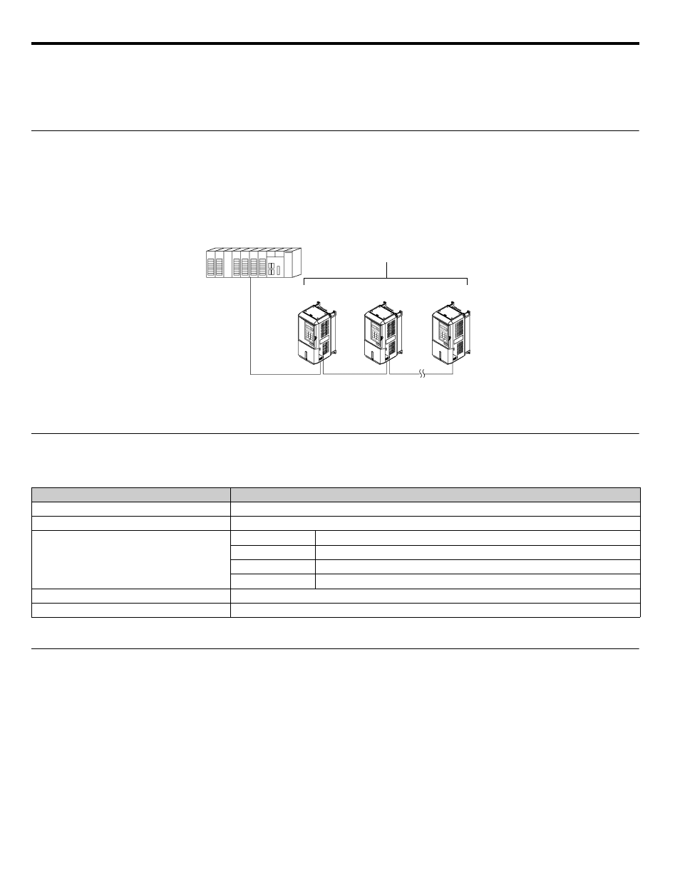
Modbus communication is configured using 1 master (PLC) and a maximum of 31 slaves. Serial communication between master and
slave is normally initiated by the master and responded to by the slaves.
The master performs serial communication with one slave at a time. Consequently, the slave address of each slave must be initially set, so
that the master can perform serial communication using that address. Slaves receiving commands from the master perform the specified
functions, and send a response back to the master.
Figure D.1 Example of Connections between Master and Drive
◆ Communication Specifications
The Modbus communication specifications are shown below:
Table D.1 Modbus Communication Specifications
◆ Communication Connection Terminal
Modbus communication uses the following terminals: S+, S-, R+, and R-. The terminating resistance must be turned ON only if the
iQpump drive is at the very end of the Serial Communication chain. Set the terminating resistance by turning ON pin 1 of switch S1.
Item
Specifications
Interface
RS-422, RS-485
Communications Cycle
Asynchronous (Start-stop synchronization)
Communications Parameters
Baud rate:
Select from 1200, 2400, 4800, 9600, and 19200 bps.
Data length:
8 bits fixed
Parity:
Select from even, odd, or none.
Stop bits:
1 bit selected
Communications Protocol
Modbus
Number of Connectable Units
31 units max.
Master
iQpump
iQpump
iQpump
Slaves