8 main circuit test procedure, Main circuit test procedure, Warning – Yaskawa iQpump Controller User Manual User Manual
Page 155
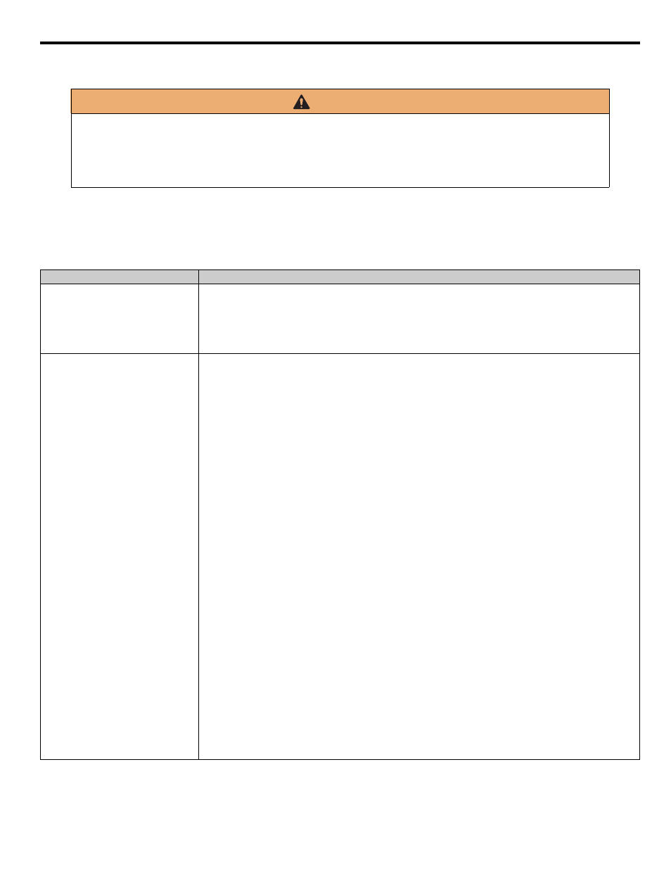
6.8 Main Circuit Test Procedure
YASKAWA TM.iQp.06 iQpump Controller User Manual
155
6.8
Main Circuit Test Procedure
Before attempting any troubleshooting checks, make sure that the three-phase power is disconnected and locked out. With power
removed from the unit, the DC bus capacitors will stay charged for several minutes. The Charge LED in the iQpump drive will glow red
until the DC bus voltage is below 10 Vdc. To ensure that the DC bus is completely discharged, measure between the positive and negative
bus with a DC voltmeter set to the highest scale.
Table 6.7 Main Circuit Test Procedures
WARNING
Prior to removing any protective cover or wiring any part of the iQpump drive, remove all power sources, including
main input power and control circuit power. Wait a minimum of 5 minutes after power removal, before removing any
cover. The charge lamp located within the iQpump drive should be off prior to working inside. Even if the charge lamp is
off, one must measure the AC input, output, and DC Bus potential to insure safe levels prior to resuming work. Failure to
adhere to this warning may result in personal injury or death.
Check
Procedure
Measure DC Bus Voltage
1. Set the digital multi-meter to its highest Vdc scale.
2. Measure between
⊕ 1 and (-) for the following check:
Place the positive (red) meter lead on
⊕ 1.
Place the negative (black) meter lead on (-).
3. If the measured voltage is < 10 Vdc, it is safe to work inside the drive.
If not, wait until the DC Bus has completely discharged.
Input Diodes
(D1-D12 or Q1)
The input diodes rectify or transform the three-phase input AC voltage into a DC voltage.
1. Set a digital multi-meter to the Diode Check setting.
2. Place the positive (red) meter lead on terminal R/L1.
Place the negative (black) meter lead on terminal
⊕ 1.
Expected reading is about 0.5 Volts.
3. Place the positive (red) meter lead on terminal S/L2.
Place the negative (black) meter lead on terminal
⊕ 1.
Expected reading is about 0.5 Volts.
4. Place the positive (red) meter lead on terminal T/L3.
Place the negative (black) meter lead on terminal
⊕ 1.
Expected reading is about 0.5 Volts.
5. Place the positive (red) meter lead on terminal R/L1.
Place the negative (black) meter lead on terminal (-).
Expected reading is OL displayed.
6. Place the positive (red) meter lead on terminal S/L2.
Place the negative (black) meter lead on terminal (-).
Expected reading is OL displayed.
7. Place the positive (red) meter lead on terminal T/L3.
Place the negative (black) meter lead on terminal (-).
Expected reading is OL displayed.
8. Place the positive (red) meter lead on terminal (-).
Place the negative (black) meter lead on terminal R/L1.
Expected reading is about 0.5 Volts.
9. Place the positive (red) meter lead on terminal (-).
Place the negative (black) meter lead on terminal S/L2.
Expected reading is about 0.5 Volts.
10. Place the positive (red) meter lead on terminal (-).
Place the negative (black) meter lead on terminal T/L3.
Expected reading is about 0.5 Volts.11. Place the positive (red) meter lead on terminal
⊕
11. Place the negative (black) meter lead on terminal R/L1.
Expected reading is OL displayed.
12. Place the positive (red) meter lead on terminal
⊕ 1.
Place the negative (black) meter lead on terminal S/L2.
Expected reading is OL displayed.
13. Place the positive (red) meter lead on terminal
⊕ 1.
Place the negative (black) meter lead on terminal T/L3.
Expected reading is OL displayed.