10 connecting the load-shedding contactor, Connecting the load-shedding contactor – SMA SI-TB-BOX-10 User Manual
Page 44
6 Electrical Connection
SMA America, LLC
44
SI_TDBOX-IA-eng-IUS122211
Installation Manual
6.10 Connecting the Load-Shedding Contactor
Cable requirements:
☐ Conductor material: copper
☐ Minimum wire size: 18 AWG
☐ Maximum wire size: 14 AWG
☐ The cable must be approved for 167°F (75°C).
☐ The cable must be approved for AC 120 V.
Selecting a wire size:
• Choose the dimension of the wire size according to the maximum electrical current strength
which occurs at the terminals of the Smartformer (maximum electrical current strength: AC 3 A).
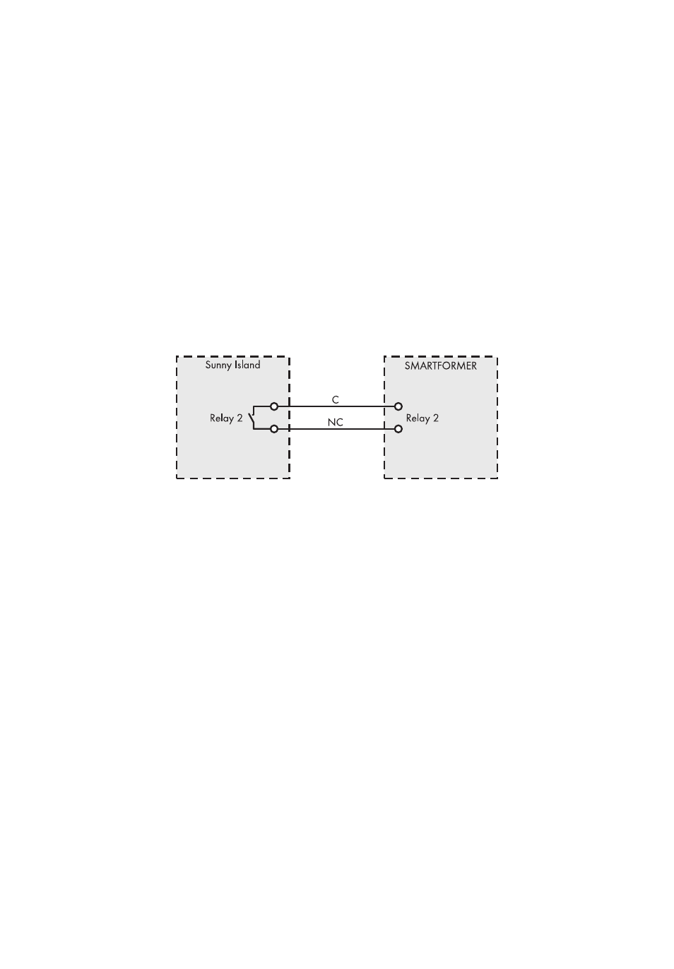
Overview:
Figure 17: Connecting the load-shedding contactor to the Sunny Island
Required tools:
☐ Screwdriver (maximum blade width: 2.5 mm)
1. Insert 2 insulated conductors into the Sunny Island and route to the terminal of the
multi-function relay 2 (see technical description of the Sunny Island).
2. Connect both insulated conductors to the 3-pin terminal supplied with the Sunny Island.
Use the contacts "C" and "NC" and label the insulated conductors accordingly.
3. Tighten the terminals (torque: 5 in-lbs. … 7 in-lbs. (0.56 Nm … 0.79 Nm)).
4. Insert the terminal into the "Relay 2" connection in the Sunny Island.
5. Introduce both insulated conductors into the Smartformer (see Section 6.4).
6. Shorten both insulated conductors and strip the insulation by
3
⁄
8
in. (10 mm).