SMA SI-TB-BOX-10 User Manual
Page 39
SMA America, LLC
6 Electrical Connection
Installation Manual
SI_TDBOX-IA-eng-IUS122211
39
6.5 Connecting Insulated Conductors to Spring Clamp Terminals
Some of the terminals of the Smartformer are executed as spring clamp terminals. Always use the
following procedure when connecting an insulated conductor to a spring clamp terminal. A different
procedure applies for connecting the insulated conductors on the load-shedding contactor
(see Section 6.10 "Connecting the Load-Shedding Contactor", page 44).
Required tools:
☐ Screwdriver (maximum blade width: 5.5 mm)
1. Insert the cable (see Section 6.4).
2. Remove the coating.
3. Shorten insulated conductors by at least
3
⁄
8
in. (10 mm). This removes any damaged or
corroded conductor material.
4. Strip the insulation of the insulated conductors by
3
⁄
4
in. (19 mm).
5. Route the insulated conductors to the connecting terminal plate provided.
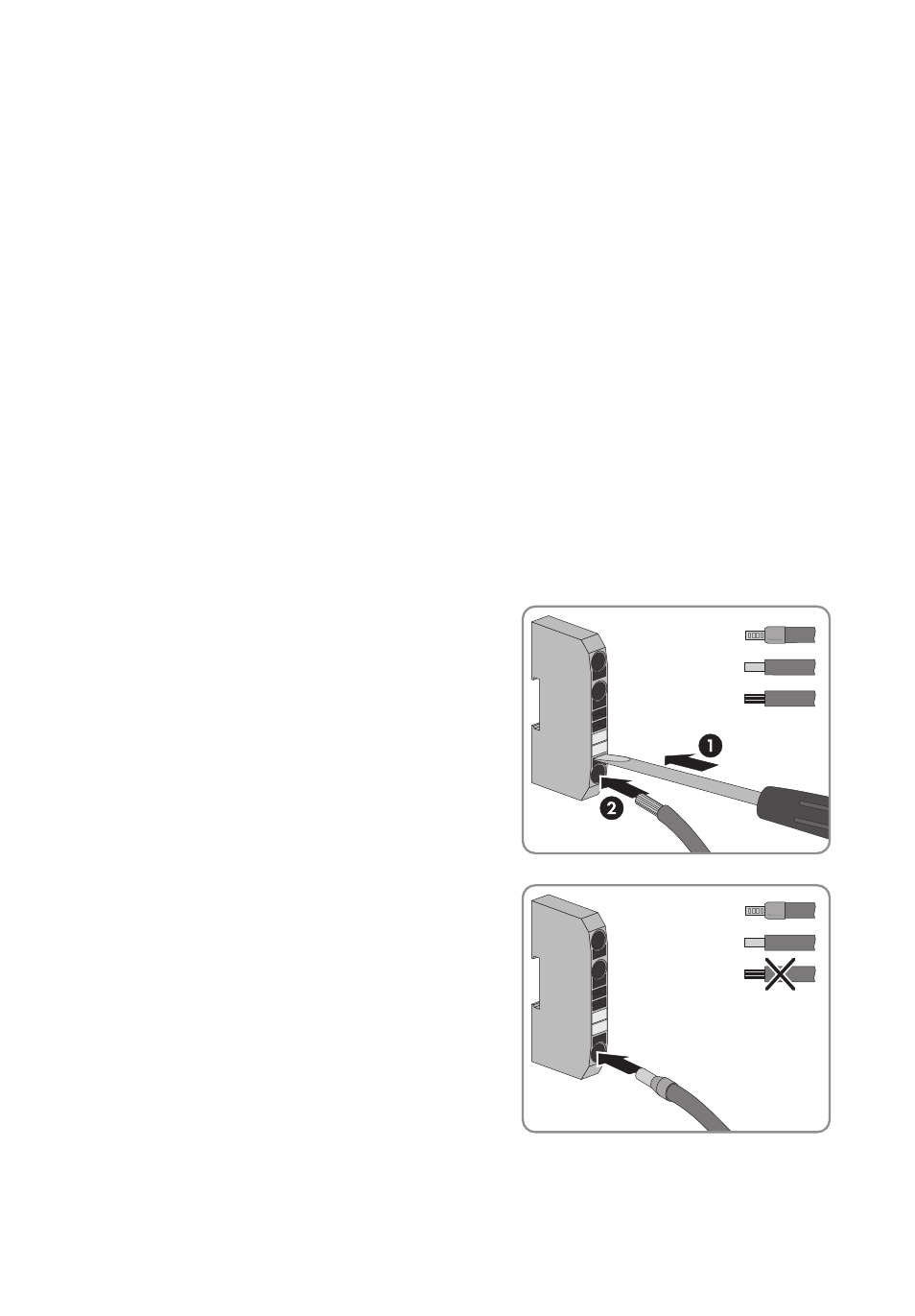
6. Connect the conductors to the spring clamp terminals. Note that there is 1 possible procedure
for a conductor with a bootlace ferrule and 1 possible procedure for a conductor made of
coarse stranded wire or solid wire:
• To connect a conductor with a bootlace ferrule,
a conductor made of coarse stranded wire or
solid wire, or a conductor made of fine stranded
wire, push a screwdriver into the terminal
contact of the spring clamp terminal and insert
the conductor into the terminal up to the limit
position.
• To connect a conductor with a bootlace ferrule
or a conductor made of coarse stranded wire or
solid wire, push the conductor into the terminal
up to the limit position.