SMA SI-TB-BOX-10 User Manual
Page 42
6 Electrical Connection
SMA America, LLC
42
SI_TDBOX-IA-eng-IUS122211
Installation Manual
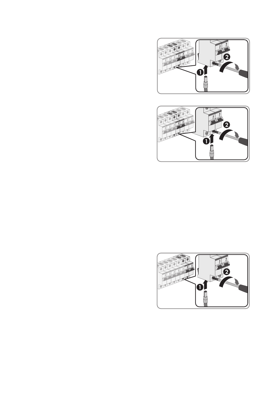
5. Connect the L1 conductor to the lower
screw terminal "Sunny Boy L1" of the miniature
circuit-breaker "F4" and tighten screw
(torque: 25 in-lbs. (2.8 Nm)). Use a torque wrench
with a PZ 2 attachment or another suitable
cross-head screwdriver attachment.
6. Connect the L2 conductor to the lower
screw terminal "Sunny Boy L2" of the miniature
circuit-breaker "F5" and tighten screw
(torque: 25 in-lbs. (2.8 Nm)). Use a torque wrench
with a PZ 2 attachment or another suitable
cross-head screwdriver attachment.
6.8 Connecting the Generator or Power Distribution Grid
When connecting to the power distribution grid, proceed as described below for the generator.
1. Connect the PE conductor to a vacant spring clamp terminal of a "Grounding" connecting
terminal plate (see Section 6.5).
2. Connect the N conductor to a vacant spring clamp terminal of a "Neutral N" connecting
terminal plate (see Section 6.5).
3. To connect a single-phase generator, connect conductor L of the generator.
• Strip the insulation of insulated conductor L by
3
⁄
8
in. (10 mm).
• Connect the L conductor to the lower screw
terminal "Grid or Generator L/L1" of the
miniature circuit-breaker "F6" and tighten screw
(torque: 25 in-lbs. (2.8 Nm)). Use a torque
wrench with a PZ 2 attachment or another
suitable cross-head screwdriver attachment.