4 system overview, System overview – SMA SI-TB-BOX-10 User Manual
Page 35
SMA America, LLC
6 Electrical Connection
Installation Manual
SI_TDBOX-IA-eng-IUS122211
35
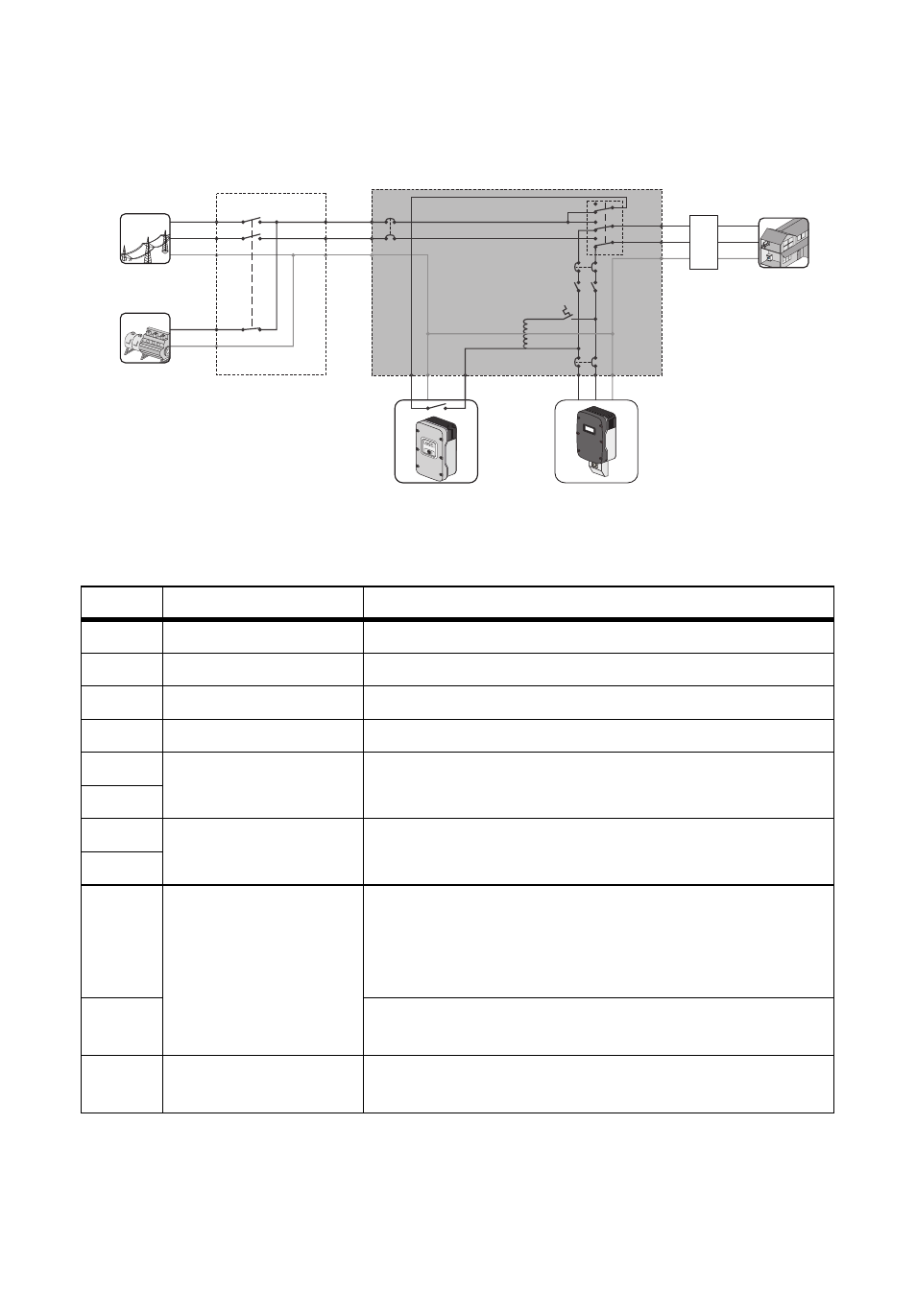
6.2.4 System Overview
Figure 16: Smartformer system overview
Position Description
Explanation
"T1"
Autotransformer
See Section 4.2 "Autotransformer", page 17
"Q1"
Overload protection
See Section 4.6 "Overload Protection", page 20
"Q2"
Load-shedding contactor See Section 4.4 "Load-Shedding Contactor", page 18
"Q3"
Bypass switch
See Section 4.3 "Bypass Switch", page 18
"F2"
2-pole miniature
circuit-breaker
When the bypass switch is set to "I ON", "F2" and "F3"
protect the loads.
"F3"
"F4"
2-pole miniature
circuit-breaker
"F4" and "F5" protect the PV inverters.
"F5"
"F6"
2-pole miniature
circuit-breaker
When the bypass switch is set to "II ON", "F6" protects the
loads and the generator.
When the bypass switch is set to "I ON", "F6" protects the
AC 2 output of the Sunny Island.
"F7"
When the bypass switch is set to "II ON", "F7" protects the
loads and the generator.
ATS
Automatic Transfer
Switch
Automatic transfer switch: not included in scope of delivery
L1
L2
N
L
N
L1
L2
N
L/AC2
N
L/AC1
L1 L2 N
L/L1
N
L2
F7
F6
F2
F3
F4
F5
T1
Q1
Q2
Q3
AC
sub-distribution
Loads
Sunny Island
PV inverter
Generator
Power
distribution grid
SMARTFORMER