2 overview of the connection area, 1 view from below, 2 view from above – SMA SI-TB-BOX-10 User Manual
Page 32: Overview of the connection area, View from below, View from above
6 Electrical Connection
SMA America, LLC
32
SI_TDBOX-IA-eng-IUS122211
Installation Manual
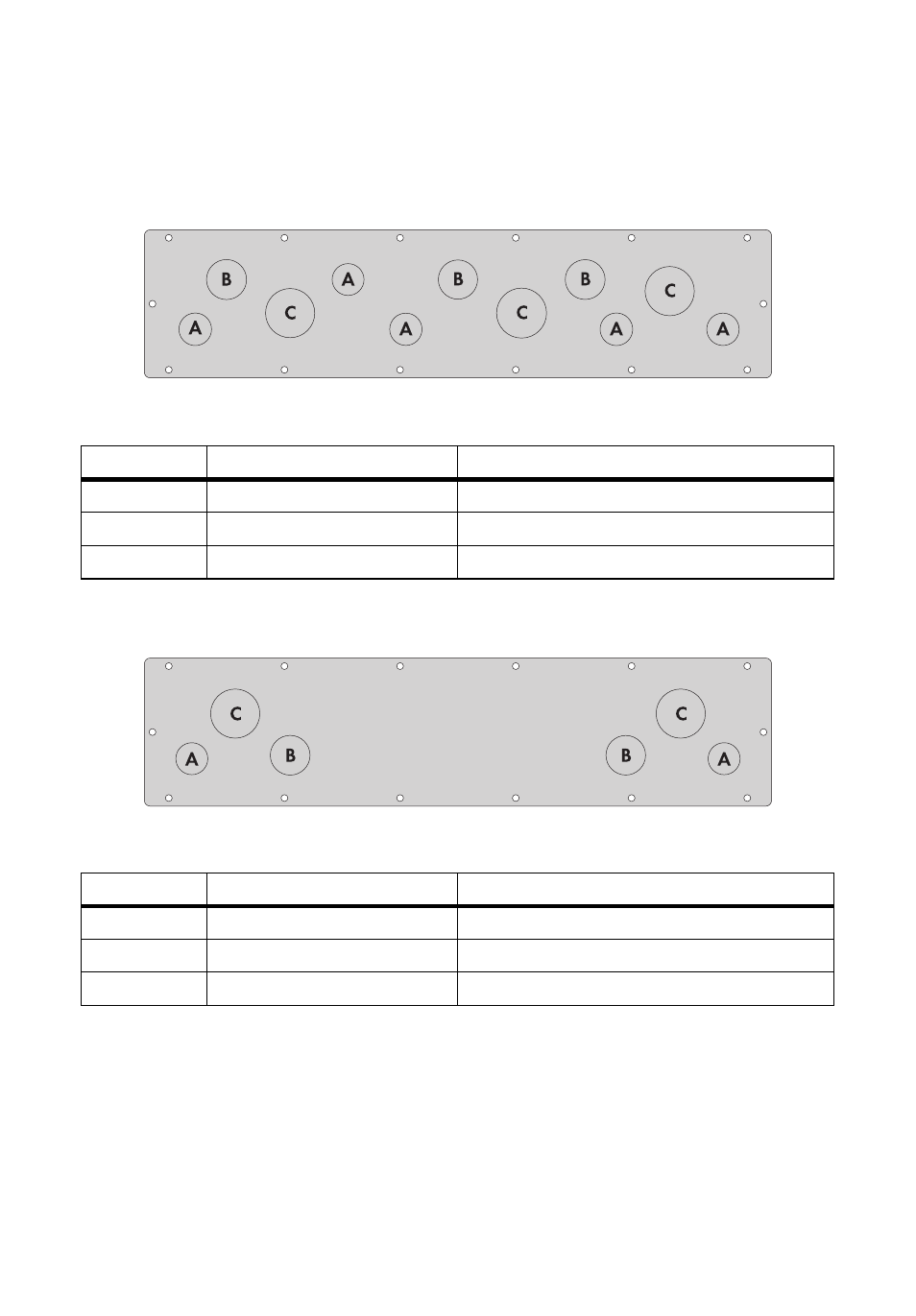
6.2 Overview of the Connection Area
6.2.1 View from Below
Figure 13: Flange plate with knockouts on the bottom of the Smartformer
6.2.2 View from Above
Figure 14: Flange plate with knockouts on the upper side of the Smartformer
Position
Description
Suitable conduit for connection (diameter)
A
Knockouts
3
⁄
4
in. (19 mm)
B
Knockouts
1 in. (25 mm)
C
Knockouts
1
1
⁄
4
in. (32 mm)
Position
Description
Suitable conduit for connection (diameter)
A
Knockouts
3
⁄
4
in. (19 mm)
B
Knockouts
1 in. (25 mm)
C
Knockouts
1
1
⁄
4
in. (32 mm)
See also other documents in the category SMA Equipment:
- SUNNY PORTAL (75 pages)
- SB 2.5-1VL-40 (60 pages)
- SB 2.5-1VL-40 Service Manual (36 pages)
- SB 240 (78 pages)
- FLX Pro 17 (12 pages)
- FLX Series GSM Option Kit (48 pages)
- FLX Series Sensor Interface Option (51 pages)
- FLX Series PLA Option (62 pages)
- FLX Series (248 pages)
- 25000TL (52 pages)
- 25000TL Installation (40 pages)
- 25000TL Service Manual (46 pages)
- CBL-DC-CMB8-10 (24 pages)
- 25000TL Quick Installation Guide (36 pages)
- STP 60-10 Replacing a Defective Fan (12 pages)
- STP 60-10 Replacing Defective Surge Arresters (12 pages)
- Webconnect Systems in SUNNY PORTAL (69 pages)
- STP 12000TL (68 pages)
- STP 60-US-10 Installation (232 pages)
- 485 Data Module Type B (24 pages)
- STP 12000TL Quick Installation Guide (28 pages)
- 1000-US (52 pages)
- STP 24000TL-US (78 pages)
- STP 17000TL (60 pages)
- STP 20000TL (2 pages)
- SB 6000TL Service Manual (46 pages)
- MULTIFUNCTION RELAY (32 pages)
- SB 5000TL (60 pages)
- SB 5000TL Quick Installation Guide (32 pages)
- FANKIT01-10 (24 pages)
- SB 7700TL-US (28 pages)
- FANKIT02-10 (24 pages)
- SB 7700TL-US Installation (96 pages)
- SUNNY MINI CENTRAL (48 pages)
- DC Disconnect Switch For SB 3800-U (32 pages)
- SB 4000-US (100 pages)
- DB-DC-DISCON (4 pages)
- SB 3800-U (86 pages)
- POWER BALANCER (28 pages)
- SB 8000-US (104 pages)
- SB 11000TL‑US (40 pages)
- SMC 11000TL (24 pages)
- SBCBTL6 (36 pages)
- SB 11000TL‑US Installation (92 pages)
- SMC 11000TL Installation (96 pages)