4 mounting the smartformer on a wooden wall, Mounting the smartformer on a wooden wall – SMA SI-TB-BOX-10 User Manual
Page 29
SMA America, LLC
5 Mounting
Installation Manual
SI_TDBOX-IA-eng-IUS122211
29
7. Tighten the screws in the wall firmly. Use a torque wrench with a suitable attachment and adhere
to the maximum torque specified for the screws used.
5.4 Mounting the Smartformer on a Wooden Wall
Additional required mounting material (not included in the scope of delivery):
☐ 4 screws that are suitable for the mounting substructure and the weight of the Smartformer
(minimum diameter:
5
⁄
16
in. (8 mm), minimum length: 1
1
⁄
2
in. (40 mm)).
Requirements:
☐ The mounting location must be defined.
☐ The 4 anchorage brackets must be mounted on the enclosure rear wall.
☐ The 4 anchorage brackets must be positioned so that each drill hole can be drilled into a stud.
1. Mark the positions of the 4 drill holes on the wall. Adhere to the dimensions of the Smartformer
with the mounted anchorage brackets (see Section 5.1 "Selecting the Mounting
Location", page 22).
2. Ensure that there are no electric lines or other supply lines in the wall behind the marked
positions.
3. Drill the holes. The diameter of each drill hole must be approx. 1 mm smaller than the diameter
of the screws used.
4. Screw the screws into the wall. Allow the screw heads to protrude at least
3
/
8
in. (10 mm) from
the wall.
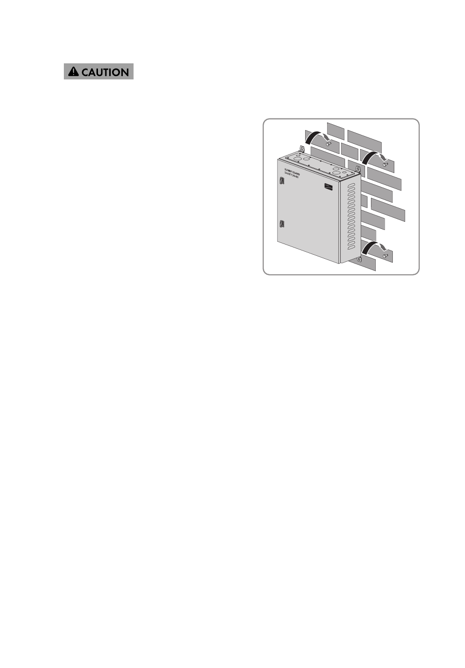
6.
Risk of injury due to falling Smartformer
Due to its heavy weight, the Smartformer can crush or break bones if it falls.
• Hang the Smartformer onto the screws and
carefully slide it into the guides of the
anchorage brackets. When doing so, note
that the weight of the Smartformer is
132
1
⁄
2
lbs. (60 kg) and make sure that the
Smartformer does not tilt or slip out of place
during mounting.