4 ac connection, Ac connection – SMA SB 6000TL‑US Installation User Manual
Page 33
SMA America, LLC
5 Electrical Connection
Installation Manual
SB6-11TL-US-IA-en-13
33
* only SB 6000TLUS-12/SB 7000TLUS-12/SB 8000TLUS-12/SB 9000TLUS-12/SB 10000TLUS-12/SB 11000TLUS-12
5.4 AC Connection
H
Sunny Boy: Output AC line terminals (N, L1 and L2)
I
AC varistor terminal with AC varistors
K
SMA DC Disconnect: Output AC line terminals (N, L1 and L2)
L
SMA DC Disconnect: Grounding electrode terminal for the connection of:
• Grounding electrode conductor
• DC equipment grounding
• AC equipment grounding
M
SMA DC Disconnect: DC+ terminal
N
SMA DC Disconnect: DC − terminal
O
DC varistor terminal with DC varistors*
P
Sunny Boy: DC − terminal
Q
Sunny Boy: DC+ terminal
R
Terminal for optional communication (RS485)
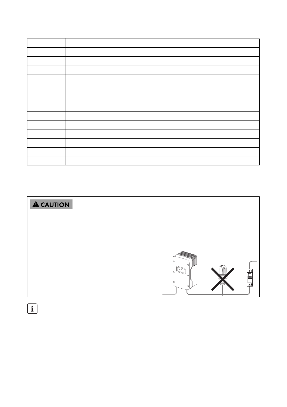
Danger of fire
Overcurrent may lead to a cable fire.
• Protect the electrical installation on the AC side. Observe the maximum fuse sizes of the
inverter types (see 11 "Technical Data", page 70).
• Do not connect more than 1 inverter to 1
miniature circuit-breaker..
• Install a separate miniature circuit-breaker for
each load. Do not connect any branch circuit
wires to the miniature circuit-breakers.
Electrical Installations
Perform all electrical installations in accordance with all electrical standards applicable locally
and the National Electrical Code
®
(NE, ANSI/NFPA 70).
See National Electrical Code
®
, Section 690-64(b) (2).
For installations in Canada, observe the applicable Canadian standards.
Position
Description