3 connection area of the sunny boy, Connection area of the sunny boy – SMA SB 6000TL‑US Installation User Manual
Page 32
5 Electrical Connection
SMA America, LLC
32
SB6-11TL-US-IA-en-13
Installation Manual
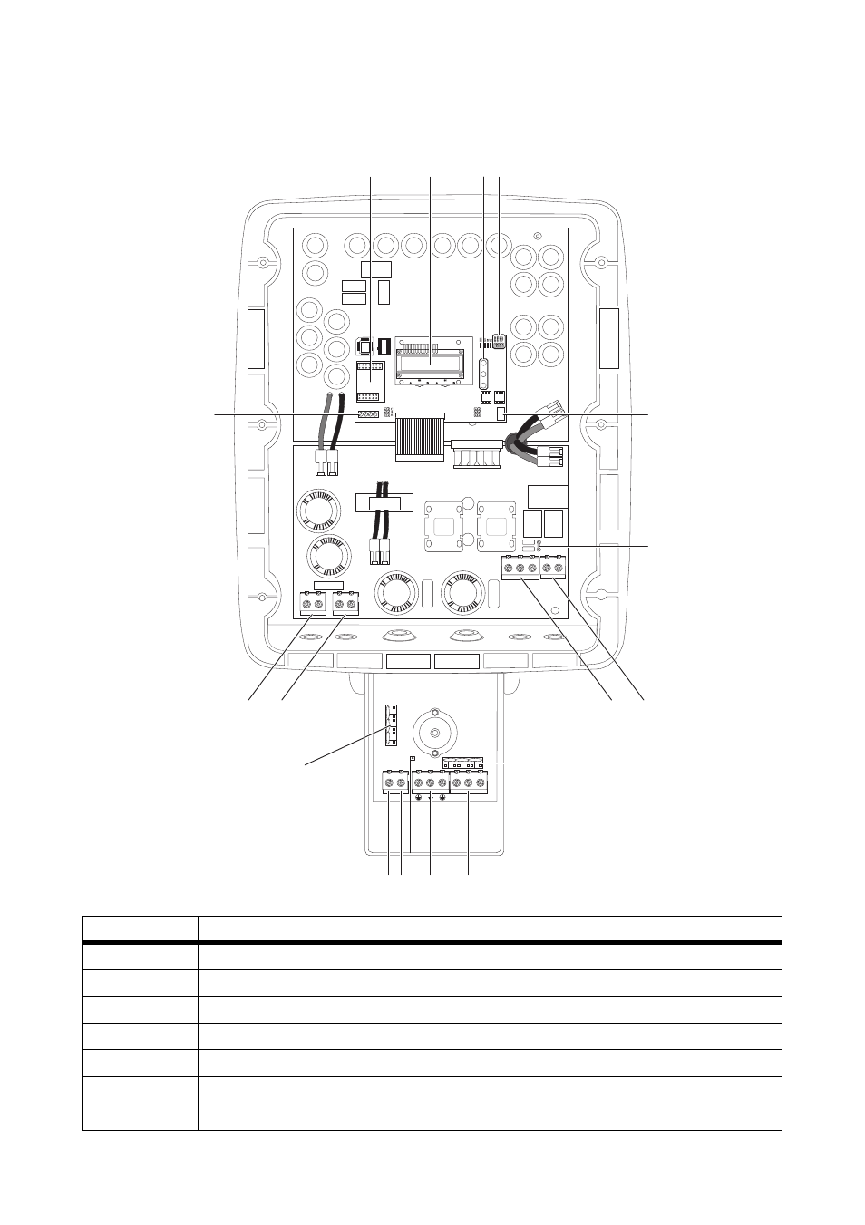
5.3 Connection Area of the Sunny Boy
Position
Description
A
Socket for optional communication Piggy-Back (RS485 or wireless)
B
Display
C
Status LEDs
D
Jumper position for verifiying the operation of the fans
E
Power Balancer terminal
F
Flat connection for grounding the cable shield for communication
G
Sunny Boy: Ground terminal (PE)
2 3 5 7
-
+
L1 L2 N
A
B
C D
G
H
K
L
M
Q
R
N
I
P
E
F
O
This manual is related to the following products: