SMA SB 6000TL‑US Installation User Manual
Page 13
SMA America, LLC
2 Safety
Installation Manual
SB6-11TL-US-IA-en-13
13
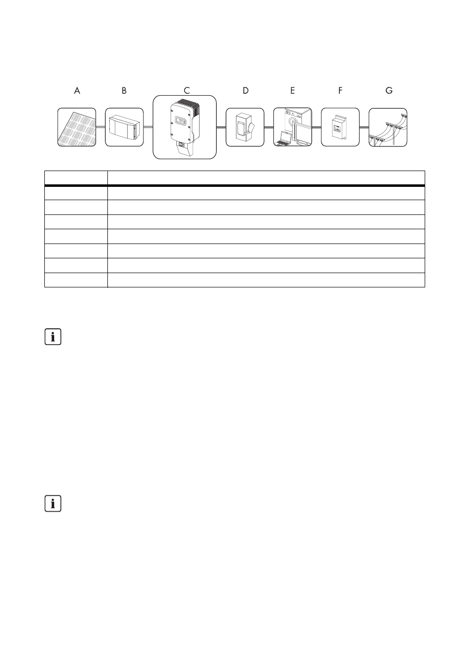
Principle of a PV Plant with a Sunny Boy
The Sunny Boy may only be operated with PV arrays (modules and cabling) that have protective
insulation. Do not connect any energy sources other than PV modules to the Sunny Boy.
PV plant design
When designing the PV plant, ensure that the values comply with the permitted operating range of all
component parts at all times. Use the free of charge "Sunny Design" at www.SMA-America.com to
design your PV plant.
Position
Description
A
PV modules
B
Sunny Boy Combiner Box
C
Sunny Boy with SMA DC Disconnect
D
AC load circuit breaker
E
Loads
F
Energy meter
G
Power distribution grid
Leading Leakage Currents
PV modules with large capacities relative to ground, such as thin-film PV modules, may only be
used if their coupling capacity does not exceed 2 µF.
During feed-in to the grid, a leakage current flows from the cells to ground. The amount of
current depends on how the modules are installed and on the weather. This leakage current
may not exceed 50 mA since otherwise the inverter will automatically disconnect from the grid.
The Sunny Boy 6000TL-US, 7000TL-US, 8000TL-US, 9000TL-US, 10000TL-US and
11000TL-US is a transformerless inverter.
It has no galvanic isolation.
The PV modules must be rated for at least the maximum PV plant voltage.