SMA SB 3000TL-US Installation User Manual
Page 40
6 Electrical Connection
SMA America, LLC
40
SB3-5TLUS22-IA-en-16
Installation Manual
Requirements for the PV Modules:
☐ The limiting values for the maximum system voltage and the maximum short-circuit current of the
inverter must not be exceeded (see Section 13 "Technical Data", page 82).
☐ The PV modules and strings connected to one input area should have the same electrical
properties based on the manufacturer information.
☐ For an optimum yield all PV modules of one input area should be mounted with the same
inclination and azimuth orientation.
Cable requirements:
☐ Solid or stranded wire of copper with no more than 19 single wires
☐ Conductor cross-section: 12 AWG to 6 AWG (5.3 mm² to 13.3 mm²)
☐ The cables must be designed in accordance with local directives and the National Electrical
Code
®
. Influencing factors for cable dimensioning are, for example, the nominal DC current,
the type of cable, the routing method, cable bundling, ambient temperature, and the maximum
desired line losses.
Additionally required mounting material (not included in the scope of delivery):
☐ Conduit fittings (
3
⁄
4
in. (19 mm)), rain-tight or for wet locations when installed outdoors
☐ Conduits (
3
⁄
4
in. (19 mm))
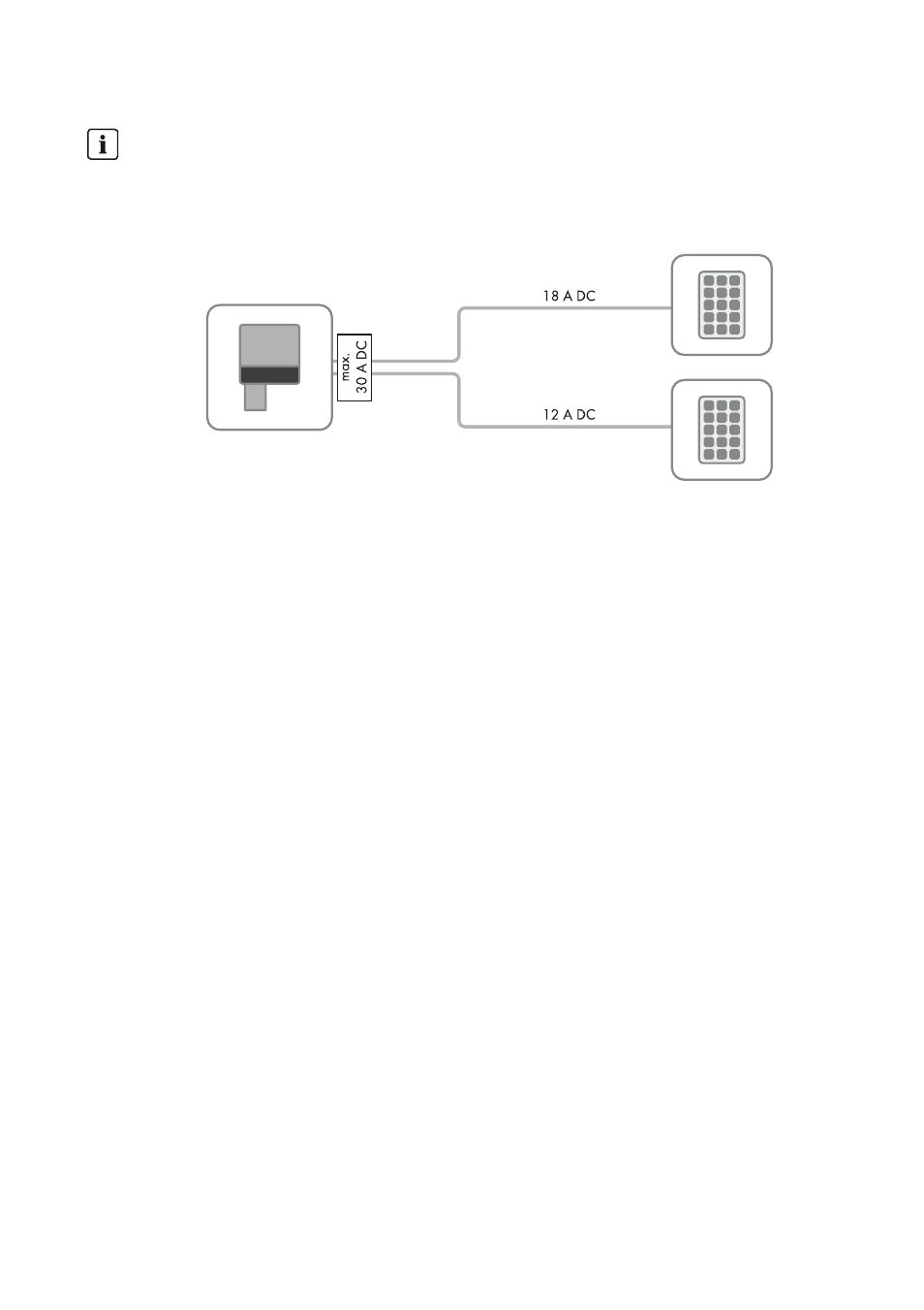
Maximum input current Sunny Boy 7000/7700TL-US
A maximum of 18 A DC is possible per DC input. The total current may not exceed 30 A DC
though.
Example:
If the maximum input current is exceeded due to the PV array design, the inverter limits the total
current to 30 A DC.