Position/true position – HEIDENHAIN ND 1400 User Manual
Page 90
76
QC-300 Series User’s Guide
Position/True position
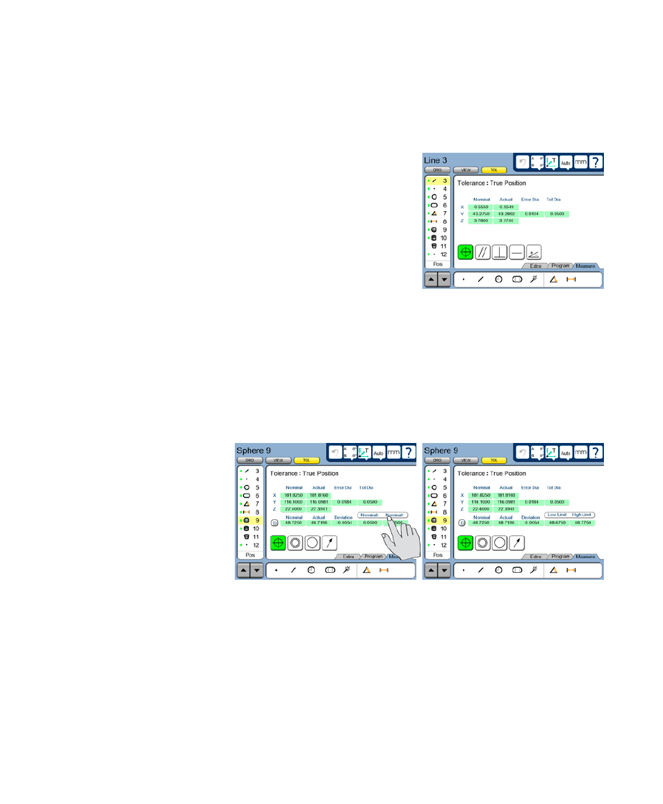
True position tolerances can be applied to points, lines, circles, arcs, spheres and cylinders.
Points and lines
The tolerance screens for points and lines are identical, and are used
to specify the acceptable deviation from the nominal feature position.
The true position tolerance compares the measured location of the cen-
ter point to the nominal center point.
Enter the nominal values into the X, Y and Z axis data fields. Enter the
allowed tolerance diameter into the Tol Dia field.
Circles, arcs, spheres and cylinders
The tolerance screens for circles, arcs, spheres and cylinders are identical, and are used to specify the
acceptable deviation from the nominal feature position, and from the nominal diameter. The true position
tolerance compares the measured location of the center point of the circle, arc, sphere or cylinder to the
nominal center point and compares the measured diameter to the nominal diameter. Touch the D (diam-
eter) or r (radius) choice field in the DRO screen to toggle between the display of diameter and radius if
desired.
Enter the nominal values into the
X, Y and Z axis and D (diameter)
data fields provided. Enter the al-
lowed Tol Dia (Tolerance diame-
ter) and feature diameter limits into
the Limit data fields as +/- ranges
or as absolute limits. Touch the
Limit data fields to toggle between
+/- ranges or absolute limits.