HEIDENHAIN ND 1400 User Manual
Page 71
57
6
Measuring
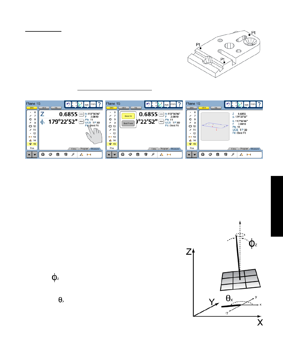
Probing planes
A minimum of three probed points are required to measure a plane.
There is no practical limit to the number of points that can be probed,
and in general accuracy is increased by probing more points.
A best fit algorithm is used to define the plane when more than three
points are probed. The plane fit to the probed data can also be changed
by selecting the desired fitting algorithm from a menu in the DRO
screen. Please refer to Chapter 12: Reference Materials for details regarding the fitting algorithms.
Measurement results are shown in the Feature list, View screen and DRO screen. The feature graphic in
the View screen shows the feature and the points used to define it. Errors are shown as whiskers connect-
ing the probed points to the feature. The maximum errors are shown in red and are used in the calculation of
form. The View screen shows location and angular displacement (shown below), form error, the number of
points used, reference frame and the projection plane (3D). When
only three points are probed, the form error is zero. When more
than three points are probed, the form error is the sum of the two
greatest opposing error magnitudes.
The angular displacements in the coordinate system orientation
shown here for a plane are designated as:
• Phi(Z) The angular displacement of the plane’s axis
from the reference frame’s Z-axis
• Theta(X) The angular displacement of the X-Y
projection of the plane’s axis from
the reference frame’s X-axis
Measuring Features
Touch the feature type...
to display the menu of alternative fit
algorithms
Probed points are shown in the
View window