Rear panel indicators, Codec board indicator, Lan connector indicator codes – Grass Valley K2 Summit Client Service Manual May.14 2010 User Manual
Page 39
09 April 2010
K2 Summit Production Client Service Manual
39
Rear panel indicators
Rear panel indicators
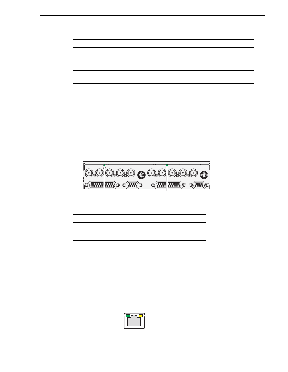
The following indicators are visible from the rear panel view.
Codec board indicator
Each channel has a green/red LED that indicates the status of the Real Time Processor
(RTP).
Interpret the RTP LED as follows:
LAN connector indicator codes
The motherboard has four RJ-45 LAN connectors that include integrated status LEDs.
The LEDs are oriented as follows:
Flashing Yellow pattern three
times a second.
Drive failure — An internal RAID drive has failed. If
RAID 1, the failure does not immediately impact
record/play operations. The redundant partner RAID
drive is maintaining functionality.
4
Flashing pattern alternating
Yellow/Green once a second.
Drive rebuild — If RAID 1, an internal RAID drive is
rebuilding.
5
Off
Normal — The K2 Summit Client is healthy and
operating normally.
5
LED behavior
Status condition
Green flashing at
approximately 1
second intervals
RTP is up and connected to the host
Green flashing at
greater than 1 second
intervals
RTP is not connected to the host.
Red
RTP error condition. Real Time OS is not running.
Off
Real Time OS is not running.
LED behavior
Status Condition
Priority
SDI IN1
SDI OUT1
SDI OUT2
LTC I/O
AES AUDIO
RS422
SDI OUT1
SDI OUT2
AES AUDIO
RS422
LTC I/O
SDI IN2
SDI IN3
SDI IN1
SDI IN2
SDI IN3
RTP
RTP
Green/Yellow/Orange
Green