Cabling, Genlock loop, Video input – Grass Valley 8995DNC v.1.3.0 User Manual
Page 21
8995UPC/DNC/UDX — Instruction Manual
21
Installation
Cabling
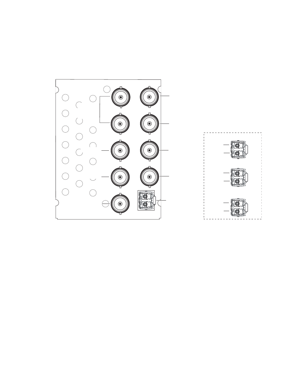
Cabling is done on the rear of the 8900UDX-R module illustrated in
. Inputs and outputs are also illustrated on the I/0 Config web page
I/O Config Web Page on page 46
Figure 7. 8995UDX Rear Module
Genlock Loop
BNCs J1 and J3 are looping inputs to the optional Genlock submodule on
the 8995 module with an external genlock reference (NTSC/PAL color
black or Tri-level sync).
Connect an external reference to J1 or J3 and loop the other input to another
device or terminate the unused input.
Video Input
The input to the module can be connected to an electrical coax BNC and up
to two fiber optic connectors depending on the fiber optic submodule
installed. Only one video input can be active at a time and must be selected
on the Video Input web page (
8480_01r3
8900UDX-R
Fiber Optic Cabling
FIBER
J1
J2
J3
J4
J5
J6
J7
J9
J8
Fiber Rx 1
Fiber Tx 2
Fiber Rx 2
J8: Video Out
Fiber Inputs/Outputs
(See Fiber Optic Cabling
at right)
J6: Video Out
J2: Auto Tracking
Delay Output
J4: Reclocked
Video Output
Fiber Optic Receiver
Fiber Optic Transmitter
Fiber Optic Transceiver
Fiber Tx 1
Fiber Rx 1
Fiber Tx 2
J1 and J3:
Genlock Ref
In Loop
J5: Video Out
J7: Video Out
J9: Video Input