Described in the following section, Ä ‘terminal – REMKO EFS 25-35 User Manual
Page 29
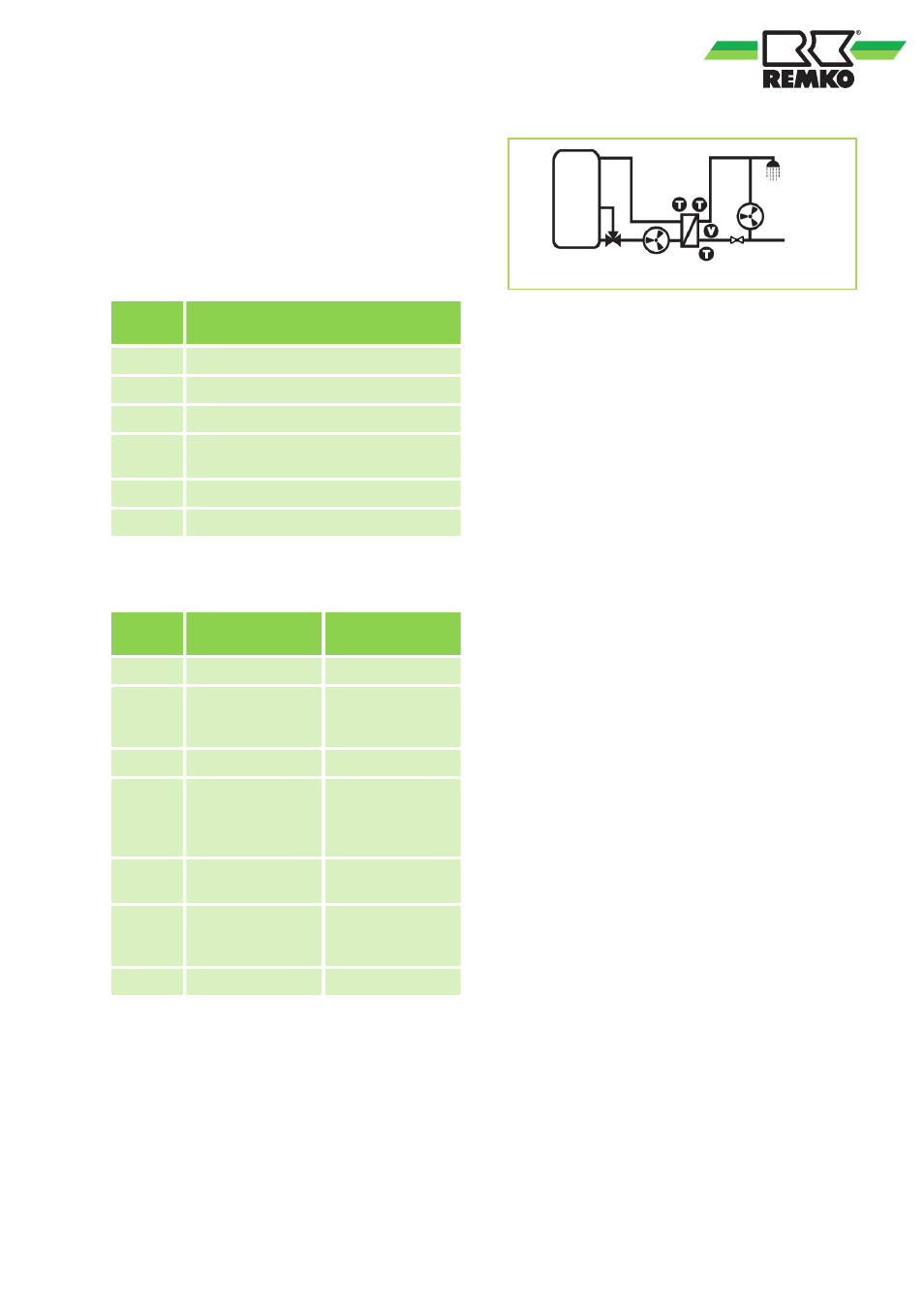
Terminal assignment
The following tables and circuit diagrams describe
assignment of the external components (pumps,
probes) to the controller terminals of the corre-
sponding Friwa variant.
Inputs
Ter-
minal
Individual operation / cascade oper-
ation
1,
^
Inlet temperature, primary (TVL)
2,
^
---
3,
^
---
4,
^
Cold water temperature, secondary
(TKW)
E.1, T
Hot water temperature, secondary
E.1, V
Medium flow rate, secondary
Outputs
Ter-
minal
Individual opera-
tion
Cascade opera-
tion
R1, N
---
Switching valve
R2, N
Return valve
(optional)
Return valve
(optional, on
master controller)
R3, N
---
---
L
const
, N
Primary pump,
secondary pump
(circulation)
Primary pump,
secondary pump
(circulation, on
master controller)
PWM
R1,
^
Primary pump
Primary pump
PWM
R2,
^
Secondary pump
(circulation)
Secondary pump
(circulation, on
master controller)
Rs, Rs
Alarm
Alarm
E.1
E.1
1
4
R2
R1
L
const.
PWM (R)2
L
const.
PWM (R)1
Fig. 32: The active R1 valve is not displayed in the
controller display.
29