REMKO EFS 25-35 User Manual
Page 27
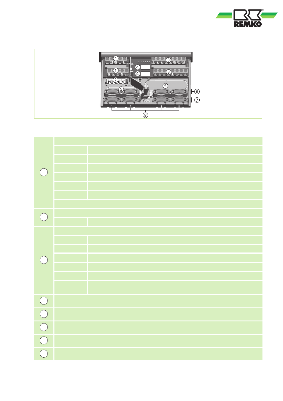
Position of the connection terminals
R3
E1
E2
Fig. 29: Connection terminals in the lower part of the controller (terminal cover removed)
1
Terminal block power supplies:
L
1x phase conductor (power input)
R1,
Output (TRIAC, for pumps or valves)
R2
Switch contact REMKO RES valve (black)
R3
Output (relay, for pumps or valves)
L
const.
2x phase conductors, live phase REMKO RES valve (brown)
N
4x neutral (combined neutral, REMKO RES valve (blue)
NOTE: Outputs R1 and R2 are protected by an electronic fuse.
2
Terminal block earth conductor:
PE
4x safety earth (combined safety earth for terminal block power supplies)
3
Terminal block signals:
1-4
4x probe input (temperature probe Pt1000)
5
1x communication connection for cascading
R
S
1x signal output (potential-free relay contact for protective low voltages)
PWM R1
2x control outputs (control for high-efficiency pumps)
PWM R2
Connection: PWM = brown,
^ = blue
^
7x ground (combined ground for probe inputs and communication connections,
as well as control outputs)
4
Multi-pin connector, only for internal use, 2 x input for REMKO FlowSonic (white)
5
Cable openings on the back of the housing
6
Top strain reliefs (2 identical plastic bridges, each with 2 strain reliefs; included in the delivery)
7
Bottom strain reliefs
8
Cable openings on the underside of the housing
27