OnLine Power PBC I User Manual
Page 9
• Alarm Signals
Also providing information on the unit’s status/particular aspects to the outside world by way of electrical
signals is a DB-9 connector. This DB-9 connector is on the front console of the Electronic Tray. The interface
provides a set of open and closed contacts, which relate the status of PBC to the outside world. An interface
DB-9 connector and cable permit the unit to bring out the following signals with their normal state (open or
closed). If the contact is not energized and the contact is closed, it is named "Normally Closed". If the contact
is not energized and the contact is open, it is named "Normally Open".
• Inverter LED is “ On ” the relay contacts are Normally Open (NO).
• Loss of Input Power, AC LED is “ Off ” the relay contacts are Normally Closed (NC).
• Low Battery LED is “ On ” the relay contacts are Normally Open (NO).
• Intrusion Switch, when the door is open the switch contacts are Normally Closed (NC).
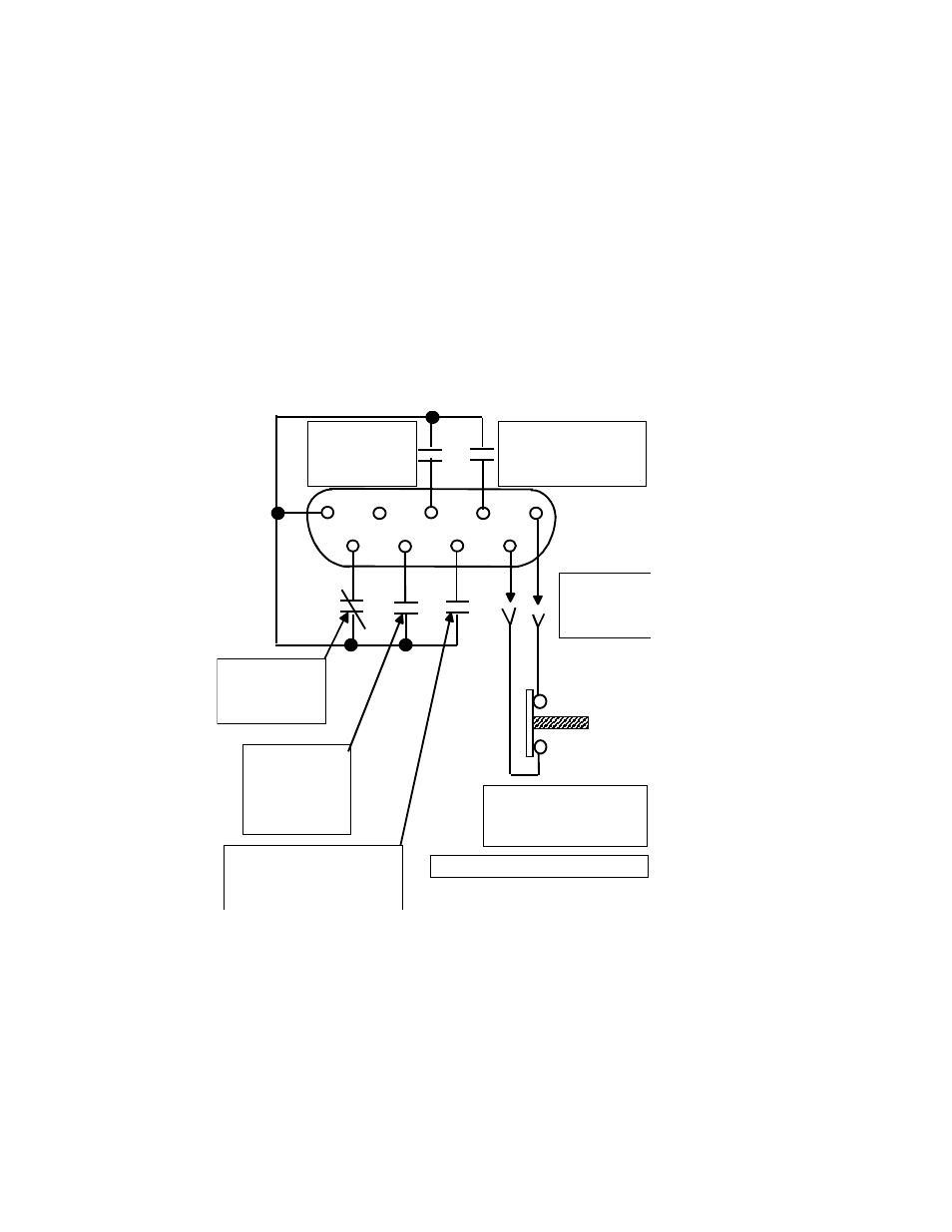
For the detailed pin out for the DB-9 connector see Illustration 1-2 below.
5 9 4 8 3 7 2 6 1
CN 304
DOOR
CIRCUIT
SW 2
DOOR SWITCH
NORMALY CLOSED
ALARM
K 3 RELAY
9 & 13 NO
" ON " BATTERY
K 5 RELAY
9 & 13 NO
AC " OFF "
K 1 RELAY
11 & 13 NC
INVERTER
" ON "
K 2 RELAY
9 & 13 NO
LOW BATTERY
K 4 RELAY
9 & 13 NO
DETAIL OF CONTACTS
Relays are dry contacts rated 2 AMPS @ 250 VAC
Illustration 1-2: DB-9 Connector
2