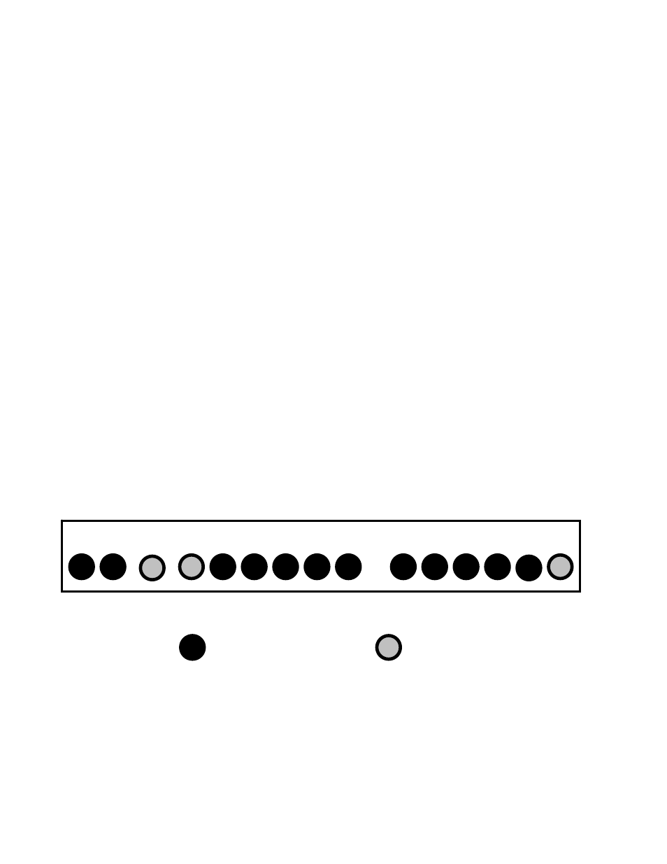
Electronic tray - status panel, Illustration 1-1 – OnLine Power PBC I User Manual
Page 8
SECTION 1 - UNIT OPERATION AND FEATURES
1-1 Overview
Within each Power Backup Cabinet is an Uninterruptible Power Supply (UPS). The purpose of this device is to
provide power to the critical load during brown out, or black out conditions, without disruption of operation of the
load equipment. When the unit operates in the backup mode, the AC power for the load comes from a set of
internal batteries and Inverter. The battery charger keeps the batteries charged and ready to fulfill the unit's
function to supply reserve power.
Also, these cabinets provide an additional level of power protection from transients, surges, electrical noise, and
other power disturbances.
What differentiates this PBC from, off-the-shelf, UPS equipment is the high level to which these units have been
“hardened” (ruggedized) to ensure continuous operation in very harsh environments, particularly outdoors.
1-2 Features
Status Indicators
The unit has two major component trays. The Electronic Tray contains the battery charger, Inverter circuitry, input
and output transformers, as well as the input/output terminals. The lower tray is the battery compartment. The
Electronic Tray set of indicator lamps on the front panel display the unit's operational mode. (See Illustration 1-1
below) These lamps provide a positive visual indication of specific aspects of the units functional operation. These
are as follows:
• AC
AC
On
•
INV
Inverter
On
• SUM
Summary Alarm Warning
• LB
Low
Battery
Warning
• HB and FB
Battery Voltage Level indicators.
HB shows half charge % voltage and FB Full charge % voltage.
• LL HL FL
Load Level Usage.
LL= Low level load
HL Half level load
FL Full level load,
• OL
Over Load of Unit
AC INV ALM LB HB FB LL HL FL OL
BATTERY VOLTAGE % LOAD IN % OF RATED AMPS
GREEN
LED
RED
LED
Electronic Tray - Status Panel
Illustration 1-1
1