Electronic tray - status panel, Appendix a: summary of indicators and controls – OnLine Power PBC I User Manual
Page 38
Appendix A: SUMMARY OF INDICATORS AND CONTROLS
AC - A green LED that is illuminated when utility is present.
INV - A green LED is illuminated when the inverter is operating.
ALM -A red LED is illuminating if the inverter malfunctions and is no longer supplying power to the output.
BATT - Five green LED's and one red LED that illuminates to update status of the battery energy available during
a power outage. These lamps do NOT reflect the charged status of the batteries during normal operations. Each of
the green LED 'S represents approximately 20 % of the battery reserve power available. As the battery discharge
continues, the LED 's will sequentially turn off until the red LED light comes on. This indicates a low battery
condition and the PBC will discontinue operation shortly.
LOAD - Five green LED 's and one red LED illuminate to indicate the amount of load that the inverter is powering.
Each green LED represents 20 % of the full load. As more loads are added, the inverter’s LED’s will sequentially
turn on until the red LED turns on. This indicates an overload condition and the inverter will turn off shortly (15
seconds).
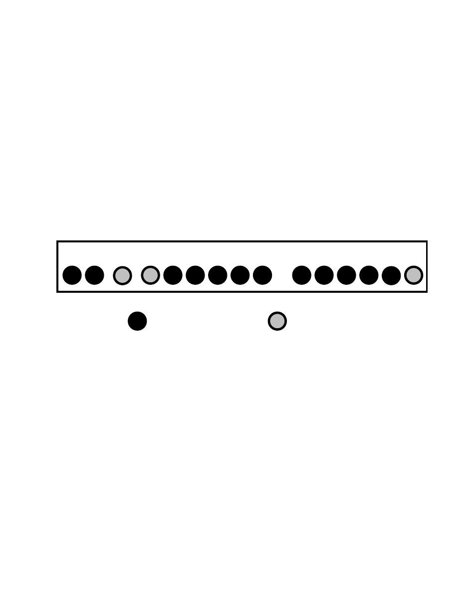
AC INV ALM LB HB FB LL HL FL OL
BATTERY VOLTAGE % LOAD IN % OF RATED AMPS
GREEN
LED
RED
LED
Electronic Tray - Status Panel
31