OnLine Power PBC I User Manual
Page 33
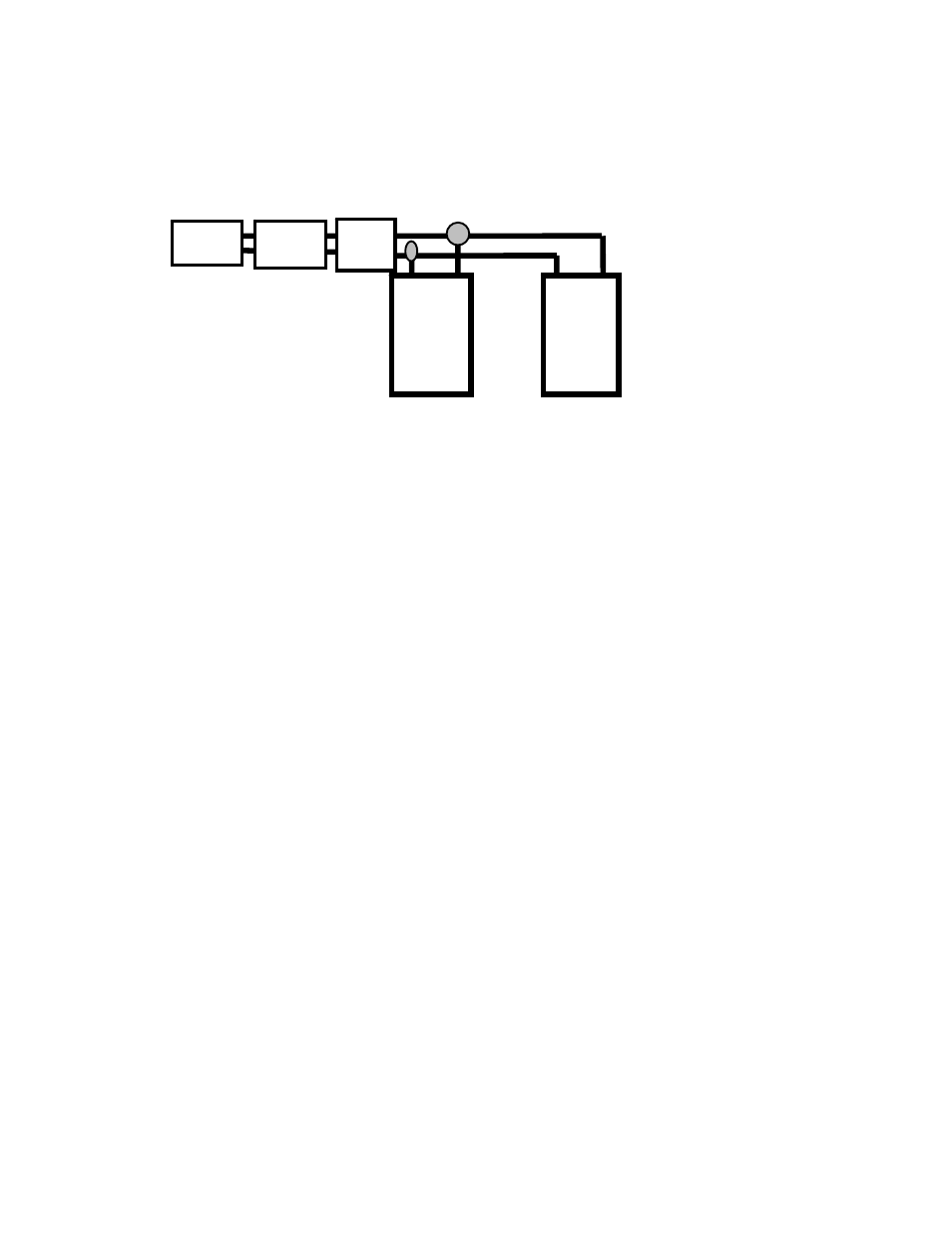
3-12 Electronic Tray, Output Wiring to Heaters:
• Heater's Input power comes through the white 2 pin socket:
• Heater's Input is 100 to 120 VAC from TB 1 input terminals 1 and 3.
• Heaters are in the bottom of the Battery Tray under the batteries.
• The Heaters connect in series as shown below, with a 2 pin plug.
2 PIN
SOCK
2 PIN
Plug
HEATER
# 1
HEATER
# 2
TB 1 - 1
TB 1 - 3
PARRALLEL WIRED
FOR 120 VAC SYSTEM
3-13 Electronic Tray, Wiring Check Out:
• Verify the input and output connections are per wiring detail in section 3-11 for the Model being in
stalled.
• Verify the input and output TB 1 & TB 2 have been torque to value below:
• Screw torque shall be 35 lbs./ in, ( 4.0 N
2
m) for TB 1 & TB 2.
• Screw torque shall be 45 lbs./ in, ( 5.1 N
2
m ) for Ground lug.
• Verify the Frequency Jumper on TB 3 is correct for the Model being installed.
See Illustration 3 - 4.
• Verify the Frequency Jumper on TB 3 is correct for the Model being installed (See Illustration 3-4).
3-14 PBC Battery Tray Connection
• Check that BLACK & RED plug from the battery tray is in the battery jack on the electronic tray.
• Engage the heater's plugs on the models with battery heaters.
3-15 PBC is ready for Normal operational check
• Check CB 1, CB 3, and CB 2 is in the “OFF" position.
• Now is the time to remove Safety Tagouts, and turn "ON " the installation Power Distribution Circuit
Breakers to " ON ".
• Measure the AC Input voltage at TB-1, is correct for the model installed.
• Turn CB1 to the “ON” position.
• Check the AC input voltage is into the PBC is proper for this Model. The Green “AC ON " LED shall be
“ ON “.
• The Green “INV ON” LED will turn “ON", after about 5 seconds.
• Turn CB 2 to “ OFF ", the Red “ LB " LED will be "OFF" and al green, battery level, LED's should be “
ON ".
• Turn CB 2 to “ ON ", the Red “ LB " LED shall turn “OFF" and Green, battery level; LED’s shall turn “
ON “. Note: From 1 to 5 Green, battery level, LED’s will be on depending on battery voltage level.
• With a Digital Voltmeter check the battery voltage across the RED & BLACK plug terminals.
• The 650W model the DC voltage shall be 48 VDC. The 1300W model the DC voltage shall be 72 VDC.
NOTE: 5 Green, battery level, LED's relate to % of battery voltage. Red "LB" led is low battery warning,
will be "ON" only when system has been on inverter for a long period of time and battery voltage has
reached the low limit set point.
26