P o l e, Side view pbc pole mounting – OnLine Power PBC I User Manual
Page 25
3-6 PBC Pole Installation
• With the successful completion of the unpacking of the PBC, proceed to next step, which is the mounting
of the unit to the pole.
• Ensure that all of the appropriate hardware is available for the mounting (See Appendix B for list of
components supplied with the Accessory Kit and ensure that Pole Mounting Brackets and hardware are
available.
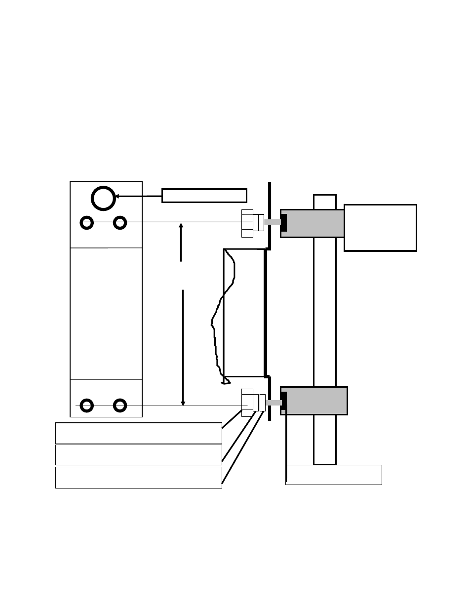
• See Illustration 3-1, which shows the mounting of the unit to the pole, and Table 3.1 for the part numbers
of the required parts.
• For the mounting of the weldments on the pole, see Illustration 3-1 for assembly details.
• Check to see the center to center spacing of the weldments is correct, and the bolt hole alignment
matches.
• Using the lifting eyes on the top of the unit, rig the unit for lifting with the PBC in balance and level from
side to side is correct.
• Install the bottom bolts first and tighten. Leave the bolt a little loose to permit some play.
• Install the top bolts and tighten, leave the bolt a little loose to permit some play.
SIDE VIEW PBC POLE MOUNTING
NUT WELDED INSIDE OF
WELDMENT
PBC
UNIT
P
O
L
E
SECTOR POLE
WELDMENT
Comcode
848126181
Hole is 0.875 ID
21.5
INCHES
LIFTING
AND
POLE
MOUNTING
PLATE
M 10-1.5 x 20 MM BOLT,
4 REQUIRED, 2 TOP 2 BOTTOM
10 MM FLAT WASHER
4 REQUIRED, 2 TOP 2 BOTTOM
10MM SPLIT LOCK WASHER
4 REQUIRED, 2 TOP 2 BOTTOM
ILLUSTRATION 3 - 1
18