Figure 38: input terminal – ping command, Table 2: bluetooth connectivity led indications – NavCom StarUtil-3000 Rev.A User Manual
Page 34
StarUtil-3000 User Guide – Rev A
Refer to Figure 37 for the steps below:
12. Select Bluetooth as the Connection Type.
13. Select the appropriate COM Port (for example, COM8; see step 8 above).
14. Click the Connect button to connect to the SF-3050.
15. Verify Bluetooth connectivity:
View the Bluetooth LED on the SF-3050 front panel. Refer to Table 2 below for
Bluetooth LED indications.
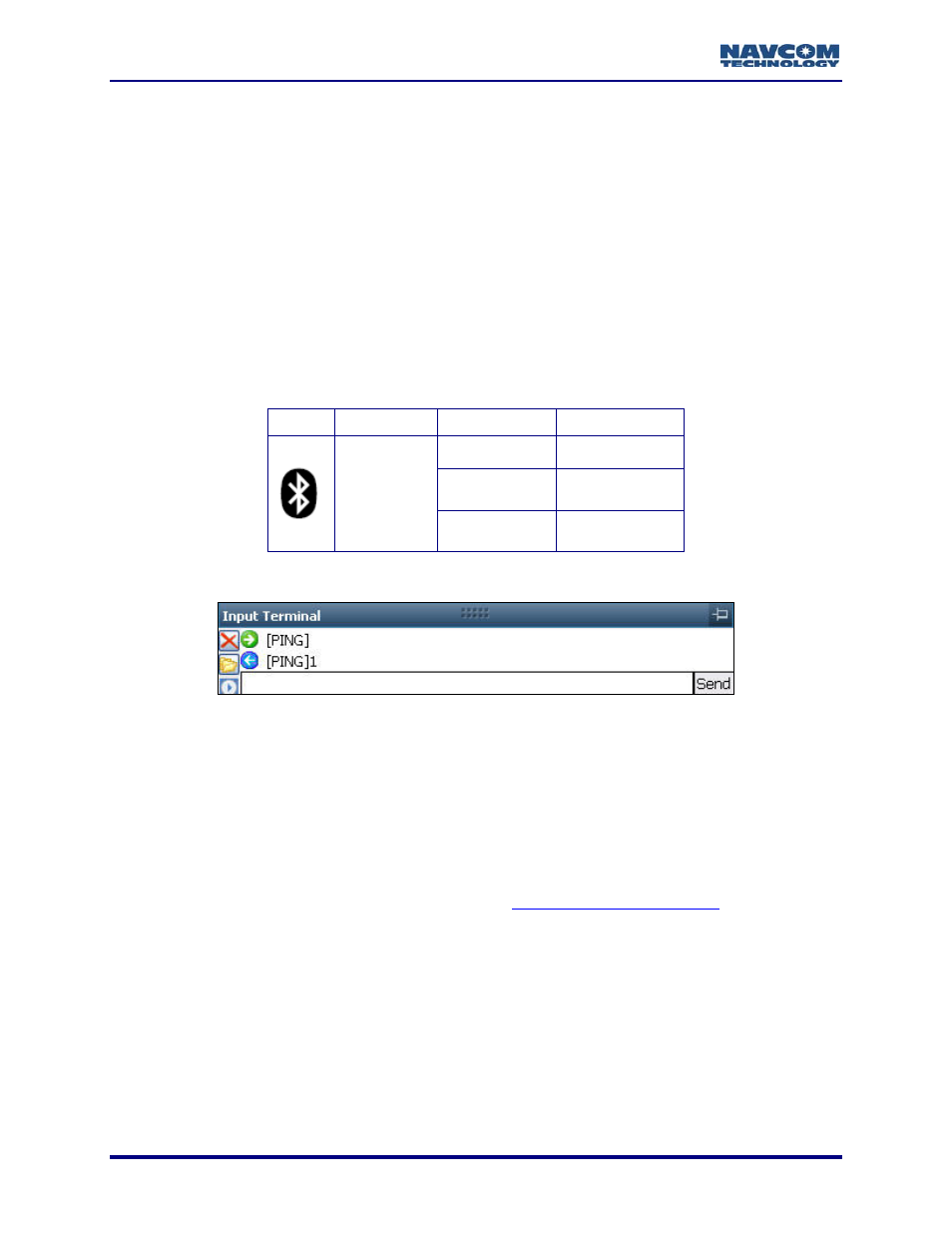
Type [PING] in the Input Terminal and click the Send button (see Figure 38). If properly
connected, the response is [PING] + current port number.
Table 2: Bluetooth Connectivity LED Indications
Icon
Indicator
Status Description
Off
Bluetooth off
Blue Blinking
Bluetooth on,
no connection
Bluetooth
Blue
Bluetooth
connected
Figure 38: Input Terminal – PING Command
How to Configure and Establish Ethernet Communications
The SF-3050 supports UDP connections in the initial release. Additional Ethernet connectivity is
planned in subsequent software releases as the product matures. This section only provides the
basic configuration for a direct Ethernet connection between the SF-3050 and a PC.
Ethernet cables are not supplied with the SF-3050. These Ethernet cables are available via a
NavCom authorized representative, or by contacting
:
Positronic 9-Pin Male to Ethernet RJ45 Plug
(P/N 94-310265-3006LF). This cable is used in the basic configuration below.
Y-Cable, Positronic 9-Pin Male to Ethernet RJ45 Plug & DB9S (RS-232/1PPS) (P/N 94-
310272-3006LF)
Refer to the SF-3050 GNSS Products User Guide for a list and descriptions of
the supplied and optional data cables (see Related Documents in the fore-
matter).
2-32